Continue to Site

Welcome to EDAboard.com

Welcome to our site! EDAboard.com is an international Electronics Discussion Forum focused on EDA software, circuits, schematics, books, theory, papers, asic, pld, 8051, DSP, Network, RF, Analog Design, PCB, Service Manuals... and a whole lot more! To participate you need to register. Registration is free. Click here to register now.

[PIC] Power factor measurement using PIC18f4520

Status
Not open for further replies.
Hi,

Using same code/circuit the system sees the fan V,I phase as 43 deg, and 0 for 200W resistive bulb.
I don't know why the system saw cap bank as resistive.
My assumption is that there is a problem in hw or sw with the pf measurement.

With inductive loads the rising edge of the voltage comes first, then the rising edge of the current. This seems to be O.K.

But with capacitive loads the rising edge of the current comes first, then the voltage. This seems to cause problems.

Check the hardware signals, check the interrupts and the resulting values..

Klaus
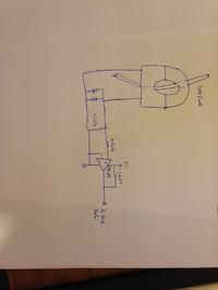
 
Hello,

The problem might be from the CT circuit:
I`m using a 10K as a Burden, and here is the aspect:

"you are asking your current transformer to drive a load of several thousand ohms plus two diode drops.
There is a term "Burden" in metering jargon that refers to the load which a current transformer is asked to drive.
A current transformer should be operated with a load as close to zero ohms as you can achieve. You measure its output with an ammeter not a voltmeter.
The higher the "burden" the less accurate the current transformer. And the greater its phase shift. Here's why.
It has certain inductance even with only a one turn primary
and voltage across its one turn primary is L di/dt of course
and voltage across its secondary is larger by the turns ratio.
Now if current is Isin(wt) , voltage is Ldi/dt = L X I X wcos(wt) and that's a 90 degree error in your phase measurement.

The correct way to operate a current transformer is with its secondary so nearly short circuited that its voltage is insignificant.
(Ideally it'd be absolutely shorted but zero ohm wire is too expensive)
That lets it produce current in secondary that's in phase with primary current
we usually measure that with an ammeter


Here is the improved version of CT circuitry:


Thanks
 

Hi,

I don't think the pf problem lies in the ct circuit.
The ct circuit works with the fan..it shows the current,
And it works with the capacitors...it shows the current.

The ct doesn't know about the phase shift between load voltage and load current.

Therefore i think it is a problem how you measure pf.

***
I don't say there is no problem with the burden...but that's another story.
Please try to solve one problem first, then the next. Try to solve it by verifying the signals step by step.

Klaus
 

Do you have a choke (high value) that can be put across the mains? you can put it in series with a 60W or a 100W lamp but measure the current and voltage across the choke only. Old type fluorescent tube chokes will be ok.
 

Hello c_mitra

I`m afraid I don't.

What is your opinion about phase shift error caused by high burden (10K) of CT, and how can this be handled?

This is another new born problem, far from knowing exact capacitance, and increasing power factor.

Still left two tasks to be done.
 

Sorry for staying out of this but my internet connection is now almost non-existent and most of the time it disconnects before I have time to post a reply.

I supect this is a case of adjusting the formula to fit the results. The phase measurement should produce a voltage after the XOR filter of 0V for 0 degrees, increasing to a maximum of 2.5V when the angle is 90 degrees (regardless of lead or lag ). I am concerned about the 'fudge factor' being so large and being a division instead of an addition or subtraction. The intention of 'fudge factor' was to correct for any signal coming from the XOR gate due to dfferences in the voltage and phase measurements within the circuit. In other words the difference being caused by inductive and RC phase shifts between the two transformers and the over-voltage protection components at the XOR input pins. Originally, when a 76S86 was used, it would compensate for the logic levels not exactly reaching 0V and VDD although that problem goes away now a CMOS gate is being used.

Before going further, I suggest a stage of debugging - with a non reactive load - measure the voltage at the XOR filter output and either add or subtract a value to make the result zero. That is the 'fudge factor' I intended. It should be a fairly small number. If scaling (multiplication or division) is required, it should be done after the zero compensation and with a 90 degree shift load in order to make the result 90. A 90 degree phase shifting load should produce a square wave at the output pin of the XOR gate which will average at VDD/2 (=2.5V) after the filter.

Brian.
 
Hi,

I don't think the pf problem lies in the ct circuit.
The ct circuit works with the fan..it shows the current,
And it works with the capacitors...it shows the current.

The ct doesn't know about the phase shift between load voltage and load current.

Therefore i think it is a problem how you measure pf.

***
I don't say there is no problem with the burden...but that's another story.
Please try to solve one problem first, then the next. Try to solve it by verifying the signals step by step.

Klaus

Klaus,

The CT circuit is working fine regarding measuring the amplitude of current. But it is in turn introducing a huge phase shift, caused by large burden.

In its datasheet the rated burden is of 200Ohm, and with it you have around 10' <<< according to this, the phase shift will be >10' as long as you increase the burden, and in my case the burden is 50 times bigger, so the phase shift should have a larger error.

I put a 10K burden since I aimed to maximumly have a load of 1A:

With the CT ratio: 10A/5mA if I put a load of 1A, I have an output voltage of 5V, which is great for ADC input channel.
I thought that putting a 200Ohm as burden, would have a severe insensitivity, since maximum load of 10Amps (which is not intended for this project) would result in a 1V to ADC input, so for lower loads, I thought that maybe the PIC won't be able to detect the <<1V voltages.

But from another part, increasing the burden revealed an increase in phase shift error that affects power factor measurement. From one bright side I had a sensitive current amplitude measurement circuit, especially thanks to your RC circuit, but from the dark side, the phase shift got majorly inductively affected.

So regarding your step by step analysis:
1) I have an error while measuring pf for capacitive load due to phase shift created by CT inductance
2) I still couldn't figure the right capacitance (that lies generally below 1uF) to correct power factor of an inductive fan, that its power factor can be accurately measured by the system.

Thanks

- - - Updated - - -

Sorry for staying out of this but my internet connection is now almost non-existent and most of the time it disconnects before I have time to post a reply.

I supect this is a case of adjusting the formula to fit the results. The phase measurement should produce a voltage after the XOR filter of 0V for 0 degrees, increasing to a maximum of 2.5V when the angle is 90 degrees (regardless of lead or lag ). I am concerned about the 'fudge factor' being so large and being a division instead of an addition or subtraction. The intention of 'fudge factor' was to correct for any signal coming from the XOR gate due to dfferences in the voltage and phase measurements within the circuit. In other words the difference being caused by inductive and RC phase shifts between the two transformers and the over-voltage protection components at the XOR input pins. Originally, when a 76S86 was used, it would compensate for the logic levels not exactly reaching 0V and VDD although that problem goes away now a CMOS gate is being used.

Before going further, I suggest a stage of debugging - with a non reactive load - measure the voltage at the XOR filter output and either add or subtract a value to make the result zero. That is the 'fudge factor' I intended. It should be a fairly small number. If scaling (multiplication or division) is required, it should be done after the zero compensation and with a 90 degree shift load in order to make the result 90. A 90 degree phase shifting load should produce a square wave at the output pin of the XOR gate which will average at VDD/2 (=2.5V) after the filter.

Brian.

Dear Brian,

You were very missed. I hope that you are doing fine.

What are your opinions about the 10K burden?

I will branch the 200W bulb, and see the voltage resultant at the output of XOR gate, then do math to make it zero. But for a maximum intended load of 1Amps, and obeying the CT datasheet, is it recommended to replace the 10K burden with 200Ohms?

From another part, what are your inspections about capacitance <1uF to improve the power factor of 60W fan? Should I increase this load, to let's say a 350W fan, to see more clear results?
Thanks
 

In general, in a given transformer, the primary and secondary waveforms are not in phase when unloaded. As the load increases, the waveforms come closer (phase difference gets reduced) but it never vanishes. But I suspect a different bug because the phase refused to change when you changed the capacitor values across the fan.
 
Before going further, I suggest a stage of debugging - with a non reactive load - measure the voltage at the XOR filter output and either add or subtract a value to make the result zero. That is the 'fudge factor' I intended. It should be a fairly small number. If scaling (multiplication or division) is required, it should be done after the zero compensation and with a 90 degree shift load in order to make the result 90. A 90 degree phase shifting load should produce a square wave at the output pin of the XOR gate which will average at VDD/2 (=2.5V) after the filter.

Brian.

When connected a 200W resistive bulb, I saw at the output of XOR gate, a value of 0.03VDC that is the fudge factor.
So I must subtract 0.03 * 1024 / 5 = 6.144 from phase angle.

What about changing the burden to rated of 200Ohms, in a way that when my load is of 1Amps, I get 0.1VDC at PORTA << Would the PIC be able to detect that value?

- - - Updated - - -

I am concerned about the 'fudge factor' being so large and being a division instead of an addition or subtraction.


Brian.

Dear Brian, the analog value for resultant XOR output when connected a non-reactive load, ranged from -0.02 to -0.03 therefore I must ADD 0.03 * 1024 / 5 to the code.

What shocks me is the presence of number 0:

Still using old posted code, where the fudge factor is eliminated by division and no addition/subtraction were present, the number 0 pop up for the non reactive load, knowing that there still a fudge factor which is not yet been eliminated.

This means that the PIC is not recognizing this fudge factor of -0.03VDC maybe because of its small value.

Thank you
 

When connected a 200W resistive bulb, I saw at the output of XOR gate, a value of 0.03VDC that is the fudge factor.
So I must subtract 0.03 * 1024 / 5 = 6.144 from phase angle.
The real calculation is (ADC Value * (5/1023)) - 0.03.
As the smallest value the ADC can measure (one LSB value) is ~0.00488V it is reasonable to mathematically correct it that way. You can then calculate the angle based on 90 degrees = 2.5V so the conversion factor is 90/2.5, in other words the angle in degrees is (corrected voltage * 36). If you want to do it directly in radians so Oshonsoft trig functions are easier, use 1.571/2.5 = 0.628 instead of 36.
Dear Brian, the analog value for resultant XOR output when connected a non-reactive load, ranged from -0.02 to -0.03 therefore I must ADD 0.03 * 1024 / 5 to the code.
I'm not sure how you can get a negative voltage out of a logic gate when it only has a positive supply. I suspect some ground voltage differences in your circuit whic might also account for the strange interrupts you noticed.

I agree that for small voltages the 10-bit ADC in the PIC is a limiting the accuracy. The only way around that is to double the phase sensor input voltage or halve the ADC reference. Even accepting it's 5V reference, 0.1V still gives an ADC value of ~20 though so it is quite capable of measuring such low voltages.

As pointed out, using a lower burden resistance will also reduce the phase errors in the transformers for a given load current.

Brian.
 

The real calculation is (ADC Value * (5/1023)) - 0.03.
As the smallest value the ADC can measure (one LSB value) is ~0.00488V it is reasonable to mathematically correct it that way. You can then calculate the angle based on 90 degrees = 2.5V so the conversion factor is 90/2.5, in other words the angle in degrees is (corrected voltage * 36). If you want to do it directly in radians so Oshonsoft trig functions are easier, use 1.571/2.5 = 0.628 instead of 36.

I'm not sure how you can get a negative voltage out of a logic gate when it only has a positive supply. I suspect some ground voltage differences in your circuit whic might also account for the strange interrupts you noticed.

I agree that for small voltages the 10-bit ADC in the PIC is a limiting the accuracy. The only way around that is to double the phase sensor input voltage or halve the ADC reference. Even accepting it's 5V reference, 0.1V still gives an ADC value of ~20 though so it is quite capable of measuring such low voltages.

As pointed out, using a lower burden resistance will also reduce the phase errors in the transformers for a given load current.

Brian.


Dear Brian,

Thank you!

I plugged 12uF with two 100K 2W series bleeding resistors across it. This was my load.
The resultant phase was 0. I grabbed a DVM to see the output of the XOR gate, that you said it shall be around 2.5V:

I saw it almost 0V!

The voltage input was around 5.5VDC for first channel of XOR gate, and the current input was around 3.5VDC for second channel of XOR gate, hence 1 XOR 1 = 0 and this is the 0 I`m seeing on the third pin of 74HC86N that in turns shows on LCD.

It is assumed to output a high logic, but it showed 0 instead.

This is the error.

Thank you

- - - Updated - - -

Hello,

@betwixt perhaps there is a problem with the inputs to the XOR circuit from this:


Caution!

The two input voltages are waveforms (rectified AC) so the DVM will not measure them properly. Each signal should be clipped at Zener voltage to protect the IC but still going to zero periodically. If you picture the two waveforms exactly in step with each other, as you would get with a resistive load, the XOR inputs would go to zero simultaneously (0 XOR 0 = 0) and go high simultaneously (1 XOR 1 = 0). It is when there is a phase difference the XOR output goes high. That's how the circuit works, the phase difference produces pulses at the XOR output then the RC filter averages them so you can measure a steady voltage with the ADC. The bigger the phase difference, the wider the pulse will be and so it's average is also higher.

You really need an oscilloscope or logic analyser to check the waveforms. You also get best resolution when the waveforms have 50% high, 50% low logic levels. The accuracy is reduced if the logic low only occurs briefly near the zero crossing point because time in which the waveforms can overlap is smaller.

I have lost track of the schematic you are using at the moment, can you post the part between the AC input and the XOR gate again please so I can be sure we are talking about the same circuitry.

Brian.

edit: sorry - it is only when I posted this first I could see the image in your previous message. Can you try making a small modification please. Instead of the XOR inputs coming from the output of the bridge rectifier, can you wire them to the top of the transformer secondaries (as in the diagram) through a diode in each wire please. The diodes should have cathodes (+ end) toward the 100K resistors. What I am trying to do is make only one half cycle of the waveform reach each XOR input so they see nearer a square wave than pulses.

FVM:
According to datasheet, PIC ADC LSB is Vref/1024.
The ADC results can be between 0 and 1023, that's a range of 1024 inclusive but the maximum 1023 is FSD of 5V so each step is 5/1023 V.
 

The ADC results can be between 0 and 1023, that's a range of 1024 inclusive but the maximum 1023 is FSD of 5V so each step is 5/1023 V.

That is true, but an input of 5V will produce an overflow; maximum value it will read will be 5*(1023/1024), something like 4.99 plus.

Consider, for example, the full scale reading as 10V and the max reading 2047 (2048-1); a reading of 1024 will give 10*(1024/2048)=5V. This is needed for continuity reasons.
 

Hello,

@betwixt:

I've changed the circuit:


Into the following:


I've seen a more satisfying results as:

1) 200W resistive bulb showed a phase angle of 43deg
2) 12uF cap bank AND 60W inductive fan showed an almost equal phase angles of 22deg

The above results were using the following code:
Code:
  Adcin 2, phase
	Lcdcmdout LcdLine4Clear
	Lcdcmdout LcdLine4Home
	phasean = phase / 14.869           //This 
	phasean = phasean / 1.6            // and this were used to get an angle of ~43deg for the fan but will be changed
	Lcdout "Phase: ", #phasean
	WaitMs 4000
	phasedeg = phasean * 0.01745329    //This is to transform angle from Rad to Deg
	Lcdcmdout LcdLine4Clear
	pf = Cos(phasedeg)
	Lcdout "pf: ", #pf
	WaitMs 1000
	Endif
 

You have put very high capacitors in the output section. I suggest that you replace the 22uF capacitor by 0.2uF (or 0.01 uF; my suggestion) ceramic capacitor (in all the sections) and also remove the 6.8uF capacitor completely.

22uF capacitor with a 10K (say) will give a time constant 220 ms which is too large - we need to read the values as soon as the result changes - the time constant should be around 1 ms or less. That means that even though the output of xor changes, it is not seen by the PIC.

Also replace the bridges with low drop type diodes (this change can wait).
 
Hello,

@betwixt

I think the circuit is working in a reciprocal way:

When 200W resistive bulb is connected, theoretically, the inputs of the XOR should be both high (1) and hence the output (corresponding to phase angle) must be equal to zero. But using this circuit (attached previously) what I`m seeing is around 4.5VDC at the XOR output that corresponds to high which should be low.

Maybe the XOR IC is provoking this? Here is its nomenclature:


74HC86N
AC668 06
Un03180


**P.S** This is a new noticed problem, that shouldn't be present. The remaining problem must only be improving the power factor of the 60W fan to 0.85 LAG using shunt capacitance whose value must be calculated with PIC and displayed on LCD.

- - - Updated - - -

You have put very high capacitors in the output section. I suggest that you replace the 22uF capacitor by 0.2uF (or 0.01 uF; my suggestion) ceramic capacitor (in all the sections) and also remove the 6.8uF capacitor completely.

22uF capacitor with a 10K (say) will give a time constant 220 ms which is too large - we need to read the values as soon as the result changes - the time constant should be around 1 ms or less. That means that even though the output of xor changes, it is not seen by the PIC.

Hello c_mitra,

I removed the large 22uF from the XOR circuit output and replaced it with a 10nF, also removed the 6.8uF completely.
The result was the same.

It showed a 43° for a purely resistive load.

Note that before you told me to plug 12uF across the main to see the resultant pf, the system was working good:

showing 0.000 as a phase for the 200W bulb, and 43° for the fan.

Let me understand:

Now (with reduced capacitor values on the three ports) you are getting phase as 43 for a 200W bulb and a phase of xx (what is the value) deg for a 60W fan.

What is the phase you are getting for the 12uF capacitor put across the mains? (with the new values)

Once you make this point clear, we need to see the software part.


This became very messed up. This part is supposed to be done months ago, but still no accurate results.
For the fan, sometimes it shows 2.4 as phase angle, sometimes 40 degrees. I don't know what is happening, and base circuit is all now changed.
 

Status
Not open for further replies.

Part and Inventory Search

Welcome to EDABoard.com

Sponsor

Back
Top