Continue to Site

Welcome to EDAboard.com

Welcome to our site! EDAboard.com is an international Electronics Discussion Forum focused on EDA software, circuits, schematics, books, theory, papers, asic, pld, 8051, DSP, Network, RF, Analog Design, PCB, Service Manuals... and a whole lot more! To participate you need to register. Registration is free. Click here to register now.

[PIC] Power factor measurement using PIC18f4520

Status
Not open for further replies.
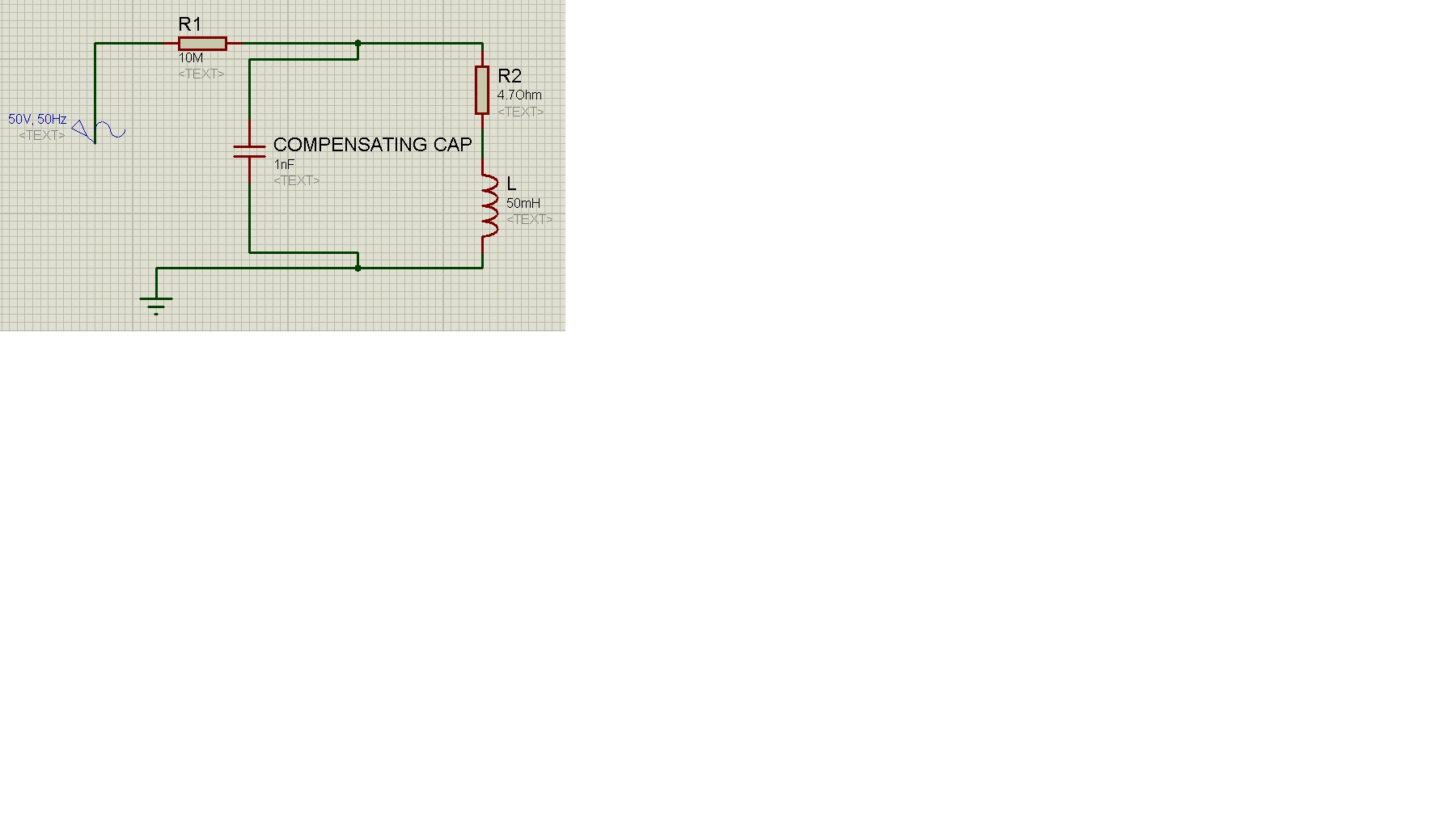
Try 20 to 200 uF as a likely range for pfc capacitors. Notice the C value in my simulation. (24.7 uF)

The website below examines an inductive load of several A, and calculates a value of 80 uF for pfc.

https://www.allaboutcircuits.com/te...nt/chpt-11/practical-power-factor-correction/

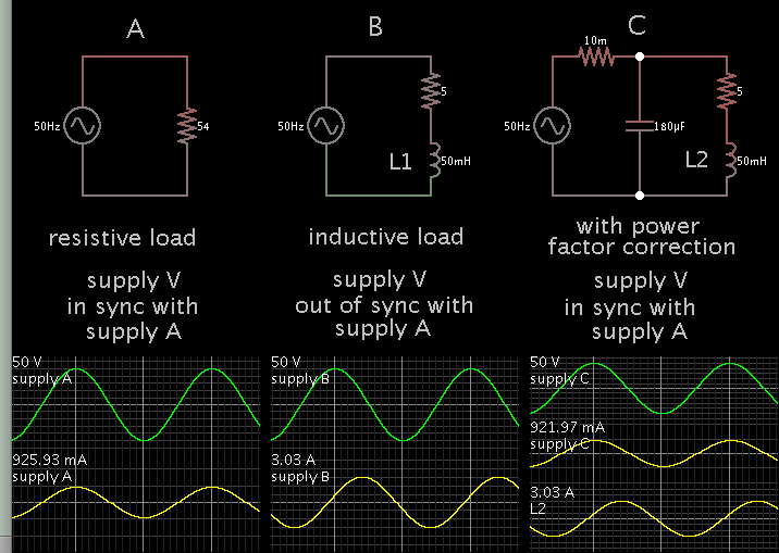
In simulation a small change can move the Ampere waveform several degrees. Suppose I start with a new load. The Ampere zero crossing wants to remain at a 'pinned' condition of 90 deg lagging or 90 deg leading. I usually need to try many C values, before I can find a range where I can make the Ampere waveform shift left and right, in relationship to the Voltage waveform.

By the way, I spoke the wrong way around in post #336, regarding current waveform advancing with inductive load, retreating with pfc capacitor.

Brad,

If 6uF over-compensated the motor, and made it draw more current, how is it supposed to act when having a shunt of 20uF and more?!
 

Hello,

I've tried the 20uF across the fan: It was waaaaaaay over-compensated, and drew a current of 1.289Amps where it was initially with no cap on, no more than 0.2Amps

So if all values above 1.5uF over-compensate the fan, and all tried series-added small caps of 50nF to 0.1uF did not affect at all the current drawing, I believe that some writers about fraud of shunt caps for domestic usage have right.

Fractional motors maybe cannot be power factor corrected, and even happened, all current taken is around 0.2Amps, so what do you expect to diminish from that drawing, at best statuses it should decrease current consumption by few milliamps, this has a large theoretical physical interpretation.

Users here (respect for them), mislead to correct capacitance value, like Brad told me to try over 20uF caps, which is way large, and c_mitra as well as Klaus had almost identical value, that all lies below 2uF.

In the market, the smallest cap value is of 1uF, I had to add MANY caps in series to reduce their capacitance, and still did not achieve any thing.


Maybe only inductive loads, powered at several horse power can be followed by application of shunt capacitance.


I have no idea what I should do about the project now, especially that PIC circuit still contains bugs and small errors.

Thanks all!
 

Hi,

The thread is so long, so I don´t remember...
If you don´t mind, please give un update:

* is it a commercial project or a hobby project?
* What exactely do/did you want to achieve?
* Is it research or do you want to build something like an automatic compensation device?
* Do you still need a solution ... or how do you want to go on with the project?

Klaus

Hello Klaus,

This is a senior project for university.
I wished to measure V, I, pf using PIC, that automatically calculate needed C for compensation, and hence turn on parallel connection between load and cap bank.

The best solution is to withdraw the whole course, and re-do it next year. I will be late for another two semesters. I've arrived to a dead end, and did not see the result of any compensation or power factor improvement.
 

Hi,

I´m very sorry for this ... the project result .. and your course delay.

***

Do you see any chance to come to a solution to prevent from loosing two semesters? Maybe with a completely new approach?


Klaus
 

Brad,

If 6uF over-compensated the motor, and made it draw more current, how is it supposed to act when having a shunt of 20uF and more?!

In an earlier post you spoke of using .1 uF. That C value resonates at 50 Hz with an inductor value of 101 H. (It is the same principle explained in c_mitra's post #339.)

So if we calculate in terms of raw math, 101 H lets through only tiny current at 230V. Therefore in real life the power factor problem is not severe, so we dismiss it rather than correct it.

When a motor draws several Amperes, then it calculates to a small Henry value, say 10mH to 100mH. The C value must resonate with this L value, at 50 Hz.

If the C value is too small or too large, then excess Amperes are drawn. This means there is a narrow band where smallest Amperes are drawn. It is not easy to find by experiment in a simulation. The C value is easier to find by calculating it. However (as you state) it is not easy to know the L value either.
 
Hi,

I´m very sorry for this ... the project result .. and your course delay.

***

Do you see any chance to come to a solution to prevent from loosing two semesters? Maybe with a completely new approach?


Klaus

Using same project title? Power factor measurement/correction using PIC?
 

So if all values above 1.5uF over-compensate the fan, and all tried series-added small caps of 50nF to 0.1uF did not affect at all the current drawing, I believe that some writers about fraud of shunt caps for domestic usage have right.
Maybe only inductive loads, powered at several horse power can be followed by application of shunt capacitance.

You have a valid point.

Very small motors, e.g., fans with 60-100W ratings, have windings made of thin wires and they act more as a resistive loads. Most of the common fans are induction motors (you can make out because they do not have brushes and commutators or slip rings) and they already have a capacitor built in as an aid to start.

Large motors, on the other hand, have rather low resistance (DC winding resistance) and high inductance. They do not use capacitors to start (three phase motors do not need capacitors) and they take large out of phase currents. As the load increases, the current comes closer to the voltage (in phase). For them, the phase correction with capacitors is not possible on an individual basis because the phase changes with load and large AC motors widely used in industry have variable and unpredictable loads. Some motors, e.g., used in large pumps, run with almost constant load and they are the ideal candidates for phase corrections.

- - - Updated - - -

The best solution is to withdraw the whole course, and re-do it next year. I will be late for another two semesters. I've arrived to a dead end, and did not see the result of any compensation or power factor improvement.

I do not recommend that. I have supervised many students but I have never seen a case when a senior university student has to take help from the outside.

I did not realise that this is a part of a course work. But I am happy that you have learnt considerable amount. I too have learnt many things in the last few months I have been here.

There is nothing wrong with your project. It is working as per your design. There are scopes for improvements and things are not perfect. I too do not understand how much of the circuit works but the principles are sound and workable.
 

Hi,

Using same project title? Power factor measurement/correction using PIC?

I didn't relate it to the forum nor the thread /title.
My concern is your course.

A new start - for me - means to start with new specifications, check several possible solutions and hopefully select the best one.

Klaus
 

Hi,


I didn't relate it to the forum nor the thread /title.
My concern is your course.

A new start - for me - means to start with new specifications, check several possible solutions and hopefully select the best one.

Klaus

Klaus,

The deadline is two weeks from today, there is no way to start a new project. Plus I've been included using this project on the list of projects almost 8 months ago.

I cannot change this now.

- - - Updated - - -

You have a valid point.

Very small motors, e.g., fans with 60-100W ratings, have windings made of thin wires and they act more as a resistive loads. Most of the common fans are induction motors (you can make out because they do not have brushes and commutators or slip rings) and they already have a capacitor built in as an aid to start.

If I buy another bigger motor of 350W would that be sufficient to correct its power factor? What is the minimum nominal power for a motor to be able to apply a shunt capacitance across it?

- - - Updated - - -

When a motor draws several Amperes, then it calculates to a small Henry value, say 10mH to 100mH. The C value must resonate with this L value, at 50 Hz.

If the C value is too small or too large, then excess Amperes are drawn. This means there is a narrow band where smallest Amperes are drawn. It is not easy to find by experiment in a simulation. The C value is easier to find by calculating it. However (as you state) it is not easy to know the L value either.


Brad,

Would a 350W instead of 60W motor will maintain shunt C, and we can experimentally see its power factor being corrected?
 

If I buy another bigger motor of 350W would that be sufficient to correct its power factor? What is the minimum nominal power for a motor to be able to apply a shunt capacitance across it?

I only have slight experience with motors of that power (about 1/2 horsepower). Its draw will be about 1A, which is a level where power factor has a significant role. However can you verify the type of motor which is suitable for a corrective shunt capacitor? Post #348 has some advice about what type of motor is suitable.

Furthermore the capacitor may or may not be accessible. (There is a difference between a capacitor-start motor, and a motor which needs pfc. I'm not sure I would be able to tell the difference myself.)

You would need to put a load on the motor (I think). If it spins freely then it draws small current. Do you have such a load handy? Probably not.

As I think about it, a refrigerator motor could be what you need, and it already is hooked up to a load which does not change much. The motor might be difficult to access, however. It may or may not be the suitable type for observing power factor.

It's possible you don't need a heavy motor. Suppose you were to operate at a lesser AC voltage (say 16V)? Hook up a 50mH coil? That would create 16 ohms of load, or 1A. (These are approximate figures.) The reduced voltage and power is easier to work with. You could observe behavior of power factor easily, and with an unchanging load.
 
Hi,

Two weeks is too short.
Maybe I was not clear. I meant the same topic "compesation" but with a new solution (hw, sw)

***
350W motor.
It depends on the current.
With no load there will be less current. (Is it possible to drive a mechanical load with the motor.)
On the other hand an unloaded motor will have the most phase shift / pf / cos(phi).
Therefore the effect of compensation will be maximized.

The "compensated" current will be low...maybe too low for your current / pf measurement.

***
Some calculation about compensation.
Imagine a complex load. You want to compensate it.
Let's say the uncompensated current is 1.1A, cos phi = 0.91
Then the phase shift is 24.6°
To compensate it to zero you need a capacitive current of 0.458A.
The resulting (compensated) current is 1.0A.

See the values: compensating from 24.6° phase shift to 0° needs more than 0.45A, but decreases the overall current only by 0.1A.
This means compensating +/-20° around zero phase shift has only marginal effect in total current.

Klaus
 

Suppose you were to operate at a lesser AC voltage (say 16V)? Hook up a 50mH coil? That would create 16 ohms of load, or 1A. (These are approximate figures.)

Simulation with lesser AC voltage. Power levels are in the tens of W, rather than hundreds of W.


The correct size capacitor improves efficiency of driving the inductive load.

These simulations are not difficult to set up. They are an enormous aid to understanding. By playing with capacitor values, you will see the effect of low or high values.

Are you saying to make a resistive voltage divider/driving a step-down transformer to tens of AC voltage and applying load across? What type of inductive load? Is it an inductor of mH or there are loads with tens of voltage needed as a supply??

This would be a genuine solution, and I won't have to buy a 1HP water pump to seek power factor behavior.
 

Hello,

Please confirm the following circuit to be used as an inductive load, where I can monitor power factor behavior, instead of using a high power rated specific motor.


If above circuit (thanks to Brad) is applicable, and "COMPENSATING CAP" can be calculated, and branched in/off the circuit it would be a great solution to see effect of shunt capacitance across inductive load, and saves cost of a several HP motor etc...

Awaiting your reply.

P.S the 50VAC will be delivered by a 220/50VAC step-down transformer, and the 4.7Ohms resistor have a 5W value, and the 10M resistor have a 2W value. Please confirm.

Thank you

- - - Updated - - -

added: the compensating cap is NOT of 1nF

- - - Updated - - -

Hello,

From another part, and IF the attached previous circuit could not be justified:

I've detached the fan, and saw its inner built-in capacitor of 2uF. The purpose of this capacitor to exist within the fan is large, but my question here is,cannot we unplug it, and compensate it with external caps on? The fan without such a capacitor needs first torque to start rotating.
 

Are you confident that your phase calculations are correct? In that case, we shall proceed to make a few test cases. Current and voltage calculations appear (with ref to expected value) correct and I guess you have made a test comparison with a conventional multimeter.

1. Get a fluorescent tube choke (old conventional ac inductor type) and record the voltage, current and phase.
2. Use 500R, 1K and 1K5 resistors in series (one at a time) and again record the voltage, current and phase.
3. Get a 5uF (400V) AC capacitor and record the voltage, current and phase.
4. Use the same 500R, 1K and 1K5 resistors in series (one at a time) and record the voltage, current and phase.

Make a graph and plot the calculated phase and observed phase for these experiments in a linear graph. Use regression analysis and report the correlation.

These details can be part of your report. If the phase calculations are correct, this will clearly show it. It will also show other errors in the measurements.
 

Simulation with lesser AC voltage. Power levels are in the tens of W, rather than hundreds of W.


The correct size capacitor improves efficiency of driving the inductive load.

These simulations are not difficult to set up. They are an enormous aid to understanding. By playing with capacitor values, you will see the effect of low or high values.


Brad,

The 10 milli-ohms resistor at beginning of the circuit can't be neglected? It is hard to find such a small resistor
 

Brad,

The 10 milli-ohms resistor at beginning of the circuit can't be neglected? It is hard to find such a small resistor

It represents some unknown theoretical resistance in the supply. Its value is not easy to determine. It is probably greater than 1/100 ohm. In house wiring it could be a few tenths of an ohm.

It also keeps the simulator happy. Otherwise it sends an error message because the capacitor is connected directly to the power source. Therefore it helps to install some theoretical inline resistance, so the simulator can calculate an RC time constant.


So this has nothing to do with real prototype circuit?
 

Status
Not open for further replies.

Part and Inventory Search

Welcome to EDABoard.com

Sponsor

Back
Top