KhaledOsmani
Full Member level 6
Right, your real-life circuit will not need a resistor in the supply leads.
Hello Brad,
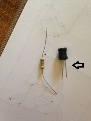
What about power rating of the ~5R resistor?
What about voltage rating of the inductor?
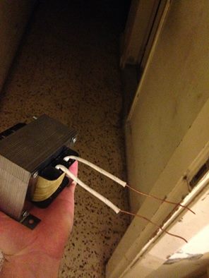
What about wiring and mm² concernings of wiring? For ~3Amps current drawing, thickness of wire loading the 220/50VAC should not be less than 3mm² , and interconnection between cap and RL circuit should also have a significant thickness.
I mean, soldering the total circuit using 0.8mm soldering wire wouldn't be a good idea. Right?