Continue to Site

Welcome to EDAboard.com

Welcome to our site! EDAboard.com is an international Electronics Discussion Forum focused on EDA software, circuits, schematics, books, theory, papers, asic, pld, 8051, DSP, Network, RF, Analog Design, PCB, Service Manuals... and a whole lot more! To participate you need to register. Registration is free. Click here to register now.

[PIC] Power factor measurement using PIC18f4520

Status
Not open for further replies.
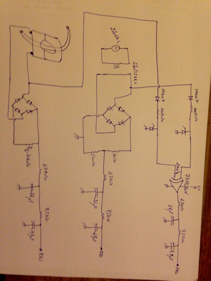
For the fan, sometimes it shows 2.4 as phase angle, sometimes 40 degrees. I don't know what is happening, and base circuit is all now changed.

Yes, this is fine. This is a software problem. But having phase angle exactly equal to zero is also a problem. Your XOR gate is working fine? You have checked that, right?
 

Yes. What must be done now? Still not knowing value of capacitance to improve power factor, also don't know if can improve pf of 60W fan.

This task is supposed to be done 2.5 months ago. Now we are seeing problems with it. I can't believe this!
 

Hi,

I see problems with the circuit:
* the XOR needs input voltage of 0.7V ... 2.0V, this is not really "zero"
* the zero cross /XOR circuits can't work properly with the rectified signals.
(For the XOR circuit one needs input signals with mains frequency and constant 50% duty cycle. With rectifying you get 2 x mains frequency. And with varying current you additionally get varying duty cycle. Below a minimum current there will be 0% dury cycle.)

But:
Both circuits give good signals for voltage magnitude and current magnitude measurement.
I don't recommend to change the filter RC values.

Klaus
 

When 200W resistive bulb is connected, theoretically, the inputs of the XOR should be both high (1) and hence the output (corresponding to phase angle) must be equal to zero. But using this circuit (attached previously) what I`m seeing is around 4.5VDC at the XOR output that corresponds to high which should be low.
No, that isn't right. Both INPUTS should be going high and low at AC frequency but it will not be a sine wave so most DVMs will show a wrong voltage measurment. The output should only be high when the inputs are DIFFERENT. (EXclusively one OR the other is high) XOR logic is like this A B OUT 0 0 0 0 1 1 1 0 1 1 1 0 So with the voltage waveform at 'A' and the current waveform at 'B', if they are in phase (both 1 or both 0) the output should be zero. Any phase difference in the waveforms will make A go high before B (or the other way around) and the output will be '1' during the time difference. The output high time is therefore proportional to the time difference (= phase shift) between them. The RC network is to average the length of the high and low output into a measurable voltage so the ADC has a chance to read it.
* the zero cross /XOR circuits can't work properly with the rectified signals. (For the XOR circuit one needs input signals with mains frequency and constant 50% duty cycle. With rectifying you get 2 x mains frequency. And with varying current you additionally get varying duty cycle. Below a minimum current there will be 0% dury cycle.)
That's why I suggested using a single diode from each transformer, it will ensure the voltage drops to zero for half of each cycle so the XOR inputs are nearer 50:50 high and low. The fix for minimum current is simple, just add a high value resistor (~2M) between the XOR inputs. It will ensure there is always voltage waveform at the inputs but will easily be overdriven by any real signal from the CT. It will give a zero phase reading if the current is too low but that is inevitable anyway, there will always be a current that is too low to measure. Brian.
 

Hi,

That's why I suggested using a single diode from each transformer, it ...
If you want to do this, then the other side of the ct needs to be grounded. But it isn't, it is floating somehow.

Klaus
 

No, that isn't right. Both INPUTS should be going high and low at AC frequency but it will not be a sine wave so most DVMs will show a wrong voltage measurment. The output should only be high when the inputs are DIFFERENT. (EXclusively one OR the other is high) XOR logic is like this A B OUT 0 0 0 0 1 1 1 0 1 1 1 0 So with the voltage waveform at 'A' and the current waveform at 'B', if they are in phase (both 1 or both 0) the output should be zero. Any phase difference in the waveforms will make A go high before B (or the other way around) and the output will be '1' during the time difference. The output high time is therefore proportional to the time difference (= phase shift) between them. The RC network is to average the length of the high and low output into a measurable voltage so the ADC has a chance to read it. That's why I suggested using a single diode from each transformer, it will ensure the voltage drops to zero for half of each cycle so the XOR inputs are nearer 50:50 high and low. The fix for minimum current is simple, just add a high value resistor (~2M) between the XOR inputs. It will ensure there is always voltage waveform at the inputs but will easily be overdriven by any real signal from the CT. It will give a zero phase reading if the current is too low but that is inevitable anyway, there will always be a current that is too low to measure. Brian.

Dear Brian,

Are you saying that using the circuit I've attached and branching a 2M one side to first input of XOR and second side to second input of XOR is the solution?

What are your comments regarding cap bank for the 60W fan?

- - - Updated - - -

@betwixt

this is the 2M between XOR inputs.

Do you have any concerns within the circuit? I`m too worried that this is supposed to be done 2 months ago, still didn't improve any power factor :(


Thats right. Something occurred to me though, it may not be a problem but it is worth a minor change to be absolutely sure: add a resistor of about 100K from the cathodes of the new diodes to ground. The reason is: when the diodes are forward conducing they lift the voltage at the input pins of the XOR gate high but when the polarity reverses, there is nowhere for any voltage stored in the circuits capacitance to discharge to. The resistors will provide a path to ensure the input pins go back to zero quickly.

Incidentaly, if you use Shottky diodes the circuit will be able to work down to lower currents. Something like a BAT85 diode will drop ~0.3V instead of the 0.6V of a normal silicon diode.

The idea behind the 2M resistor is that if there isn't enough signal from the CT, the XOR will never see it as a logic '1'. The voltage input will still be following the AC waveform though so the XOR truth table says A = always 0, B = alternating 0 and 1 so it falsely gives the impression of measuring 90 degrees. The resistor is to provide a 'weak' link so in the absence of any real current signal, it follows the voltage and gives 0 degrees as the reading. Any 'real' current signal will be able to overcome the weak link.

Brian.
 

@betwixt

Hello,

I tried the 2M between first and second channel of XOR, I think result returned better:

for the resistive lamp, it showed a phase of 0.000
for the cap bank, it showed a phase of 0.88
for the inductive fan, it showed a phase of 2.22

These values are divided by 14.869 then by 1.6 as the following code shows:

Code:
Adcin 2, phase
	Lcdcmdout LcdLine4Clear
	Lcdcmdout LcdLine4Home
	phasean = phase / 14.869           //This 
	phasean = phasean / 1.6            // and this were used to get an angle of ~43deg for the fan but will be changed
	Lcdout "Phase: ", #phasean
	WaitMs 4000
	phasedeg = phasean * 0.01745329    //This is to transform angle from Rad to Deg
	Lcdcmdout LcdLine4Clear
	pf = Cos(phasedeg)
	Lcdout "pf: ", #pf
	WaitMs 1000
	Endif

So for the fan, returning back from division, it would be 2.22 * 1.6 * 14.869 = 52.814 and Cos(52.814) = 0.604 which is reasonable

for the cap bank, returning back from division, it would be 0.88 * 1.6 * 14.869 = 20.935 << this might be a problem because it should be around 90

In this project I`m only concerned about inductive loads, to improve their pf using cap banks, no cap load is intended to be used.

So far, is this measurement working fine?

- - - Updated - - -

Thats right. Something occurred to me though, it may not be a problem but it is worth a minor change to be absolutely sure: add a resistor of about 100K from the cathodes of the new diodes to ground. The reason is: when the diodes are forward conducing they lift the voltage at the input pins of the XOR gate high but when the polarity reverses, there is nowhere for any voltage stored in the circuits capacitance to discharge to. The resistors will provide a path to ensure the input pins go back to zero quickly.

Brian.

I've added the two 100K from both new diodes to GND, but the results turned unsatisfactory:

The phase for the resistive load turned 40, when removed these two newly branched resistors, it turned back to zero.

Also, without the resistors, when connected a 100W resistive bulb instead of the 200W I see a similar phase of the inductive load, and I don't know why this happens, perhaps at lower current, CT circuitry tends to behave in a different way.
 

Still not knowing value of capacitance to improve power factor, also don't know if can improve pf of 60W fan.

Select a C value which yields the same reactive impedance as the load L value (at your operating frequency).

The aim is to make the Ampere waveform coincide with the voltage waveform.

This simulation demonstrates how pfc works with an inductive load. Alignment of V & A occurs only in the middle circuit where the capacitor of the proper value is installed. Notice the low Ampere draw. This is optimum power factor.


To get an idea how to simulate a window fan, I used my ohmmeter to measure the DC resistance of my window fan, 20 ohms. A plain ohmic resistance would draw several A. However my fan draws less than 1A. Therefore I make the load consist of a 20 ohm resistor, and 0.4 H inductor. The ohmic resistance is not as significant as the inductive impedance.

The inductor has a reactive impedance of 126 ohms.
2 * Pi * f * L

The 24.7 uF capacitor is 129 ohms.
1 / ( 2 * Pi * f * C )

These are simple formulas, although a better formula probably exists for power factor calculations.

Thanks Brad,

I did the ohm-mage test, using a multi-meter across the fan, it showed 317Ω from this value, and from knowing that the operating frequency is at 50Hz, how can one know the needed C to improve power factor?

Is it like this:

Xс = 1 / 2 * pi * 50 * C = 317 > C = 0.1uF

How one can know the real inductance of the fan? (in your example it was 0.4H)
 

I did the ohm-mage test, using a multi-meter across the fan, it showed 317Ω from this value, and from knowing that the operating frequency is at 50Hz, how can one know the needed C to improve power factor?

You also need to measure the voltage and current when the fan is running: then use V=I.Z and get the impedance.

Because they are all complex quantities, you get only the magnitude (not the phase). Now use Z^2=R^2+X^2

Once you get X, you can use your formula.
 

Hi,

It must be grounded, in any case.
But according schematic of post#326 it is not.
The negative output of the rectifier is grounded.

Klaus
 

But according schematic of post#326 it is not.
The negative output of the rectifier is grounded.

I do not understand; the output of the current transformer does not have a DC path to return anywhere- I expect it to come to ground.
 

Hi,

I just simulated the ct circuit.
I have to admit it works better than I thought.
If - only IF - the ct works about perfect, then with a secondary current of 0.15mA RMS should give good results. Not perfect, but good.
But below the 0.15mA, lets say 0.1mA, it is not able to give good results.
****
According the simulation the "digital" voltage signal at the XOR input is about 46% duty cycle. Not perfect.

Error calculation: imagine a perfect 50% duty cycle XOR-ed with a 46% duty cycle. Expect no output change from -2% to +2% phase shift.
This means +/- 7.2° around pure resistive load there is no change in output signal.

****
Please give the exact type and manufacturer of your used ct.
****
Considerations:
* It is expectable that the ct does not work perfectly with the 10k burden.
* consider a 1k or lower burden.
* consider a comparator with 200mV threshold to detect the zero cross for the current.

Klaus
 

how can one know the needed C to improve power factor?

Is it like this:

Xс = 1 / 2 * pi * 50 * C = 317 > C = 0.1uF

How one can know the real inductance of the fan? (in your example it was 0.4H)

I arrived at my crude estimates by adjusting values so the simulation gave sensible results. The 20 ohm value is a real meter reading, but the load must be more than ohmic resistance. So I assume the fan motor is mostly an inductive load. It's a broad assumption and I imagine there is more to its principle of operation.

Power factor is commonly associated with AC motors. In younger days I heard about a capacitor being installed for correction, to improve efficiency. I did not understand the theory until I experimented with the simulation as seen in my post above. The Ampere waveform advances due to inductor behavior. The capacitor is needed to bring the Ampere waveform back into alignment. It does this by storing juice during one part of the cycle, and releasing it to the load during another part of the cycle.

I understand that Brad,

The problems is that I`m not arriving at any results so far.

I've tried capacitance from 500nF to 0.1uF and still no improve in phase angle, nor diminishing the load current.
Tomorrow I will even try smaller capacitance.

Thank you

- - - Updated - - -

* It is expectable that the ct does not work perfectly with the 10k burden.
* consider a 1k or lower burden.
* consider a comparator with 200mV threshold to detect the zero cross for the current.

Klaus,

I have no aim to use a current more than the 200W bulb. The maximum current is even less than a single Ampere, this is why I enlarged the burden too much to give significant voltage at output, to be hence measured by PIC ADC.
 

Hi,

I have no aim to use a current more than the 200W bulb. The maximum current is even less than a single Ampere, this is why I enlarged the burden too much to give significant voltage at output, to be hence measured by PIC ADC.
Some ideas to improve your ct measurement:
* choose an appropriate ct
* route the "load wire" ten times trought the ct hole.
* use an amplifier at secondary side

Klaus
 

Power factor is commonly associated with AC motors. In younger days I heard about a capacitor being installed for correction, to improve efficiency. I did not understand the theory until I experimented with the simulation as seen in my post above. The Ampere waveform advances due to inductor behavior. The capacitor is needed to bring the Ampere waveform back into alignment. It does this by storing juice during one part of the cycle, and releasing it to the load during another part of the cycle.

During my younger days, we were given different (now of course I know that they are the same) explanations for the same phenomenon:

The current that flow through the inductive load is out of phase with the voltage and does less work when we compare the both in the same phase. Higher current causes greater losses in the transmission lines and domestic consumers pay by kWH (as against kVAH for the industry). It is in the interests of the power company to improve the power factor and they have installed power factor correction capacitors at regular intervals. But the best solution is of course correct at the load itself.

When you put a C against a L, you are making a resonant circuit with 50Hz - during one half cycle the C takes up the voltage from the L and then gives it back to the L in the next half. The rest of the line need not bother to supply any excess current.
 
I've tried capacitance from 500nF to 0.1uF and still no improve in phase angle, nor diminishing the load current.

Try 20 to 200 uF as a likely range for pfc capacitors. Notice the C value in my simulation. (24.7 uF)

The website below examines an inductive load of several A, and calculates a value of 80 uF for pfc.

https://www.allaboutcircuits.com/te...nt/chpt-11/practical-power-factor-correction/

In simulation a small change can move the Ampere waveform several degrees. Suppose I start with a new load. The Ampere zero crossing wants to remain at a 'pinned' condition of 90 deg lagging or 90 deg leading. I usually need to try many C values, before I can find a range where I can make the Ampere waveform shift left and right, in relationship to the Voltage waveform.

By the way, I spoke the wrong way around in post #336, regarding current waveform advancing with inductive load, retreating with pfc capacitor.
 

Status
Not open for further replies.

Part and Inventory Search

Welcome to EDABoard.com

Sponsor

Back
Top