Continue to Site

Welcome to EDAboard.com

Welcome to our site! EDAboard.com is an international Electronics Discussion Forum focused on EDA software, circuits, schematics, books, theory, papers, asic, pld, 8051, DSP, Network, RF, Analog Design, PCB, Service Manuals... and a whole lot more! To participate you need to register. Registration is free. Click here to register now.

[PIC] Power factor measurement using PIC18f4520

Status
Not open for further replies.
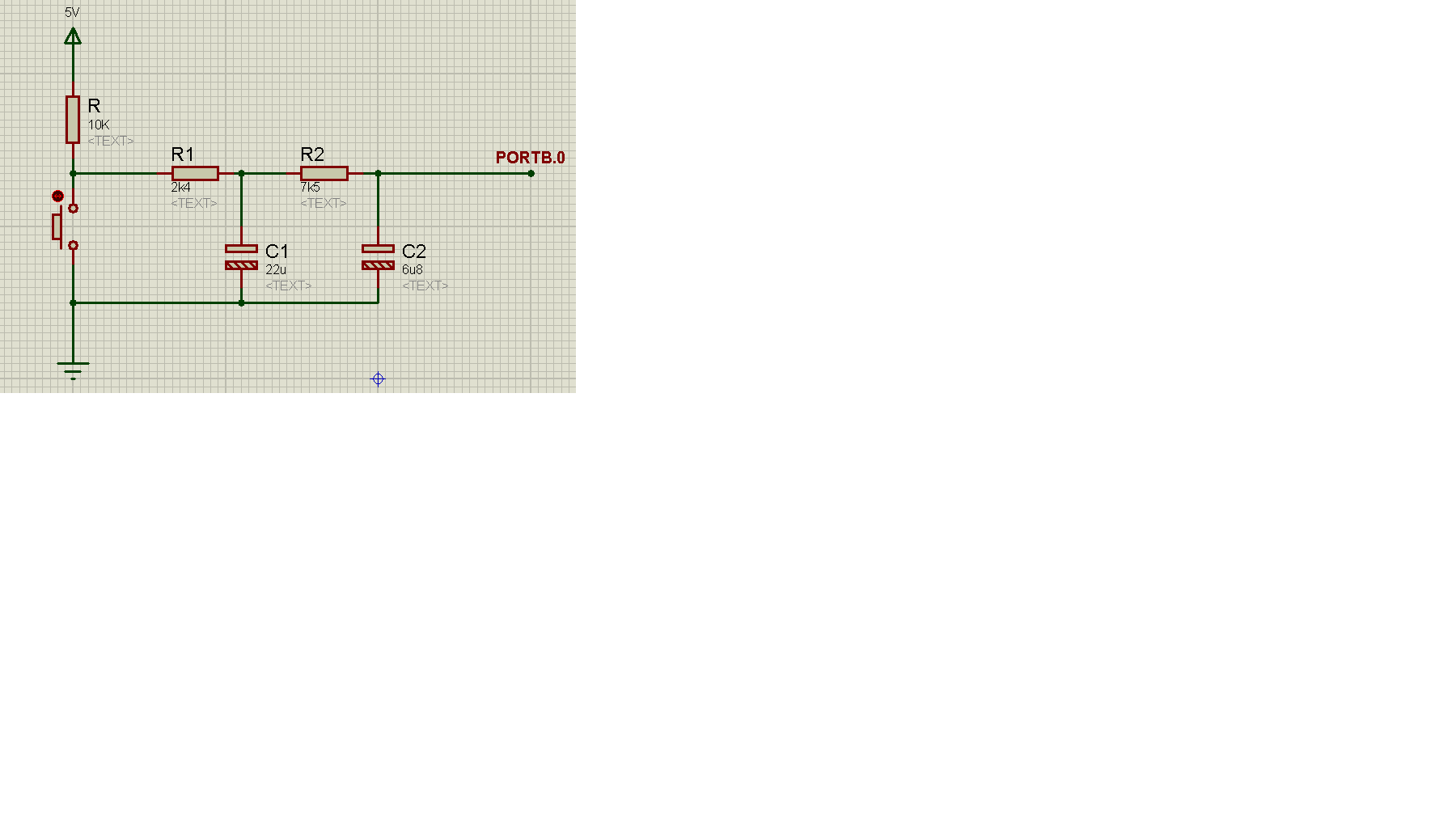
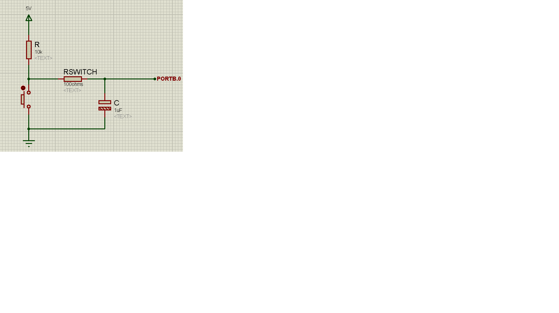
Sorry I made the same mistake as you did! Put 10R to the 5V supply and 10K to the ground (in parallel to the capacitor).

Hello c_mitra,

I changed the circuit with resistors/cap values to yours.

Result: Same.

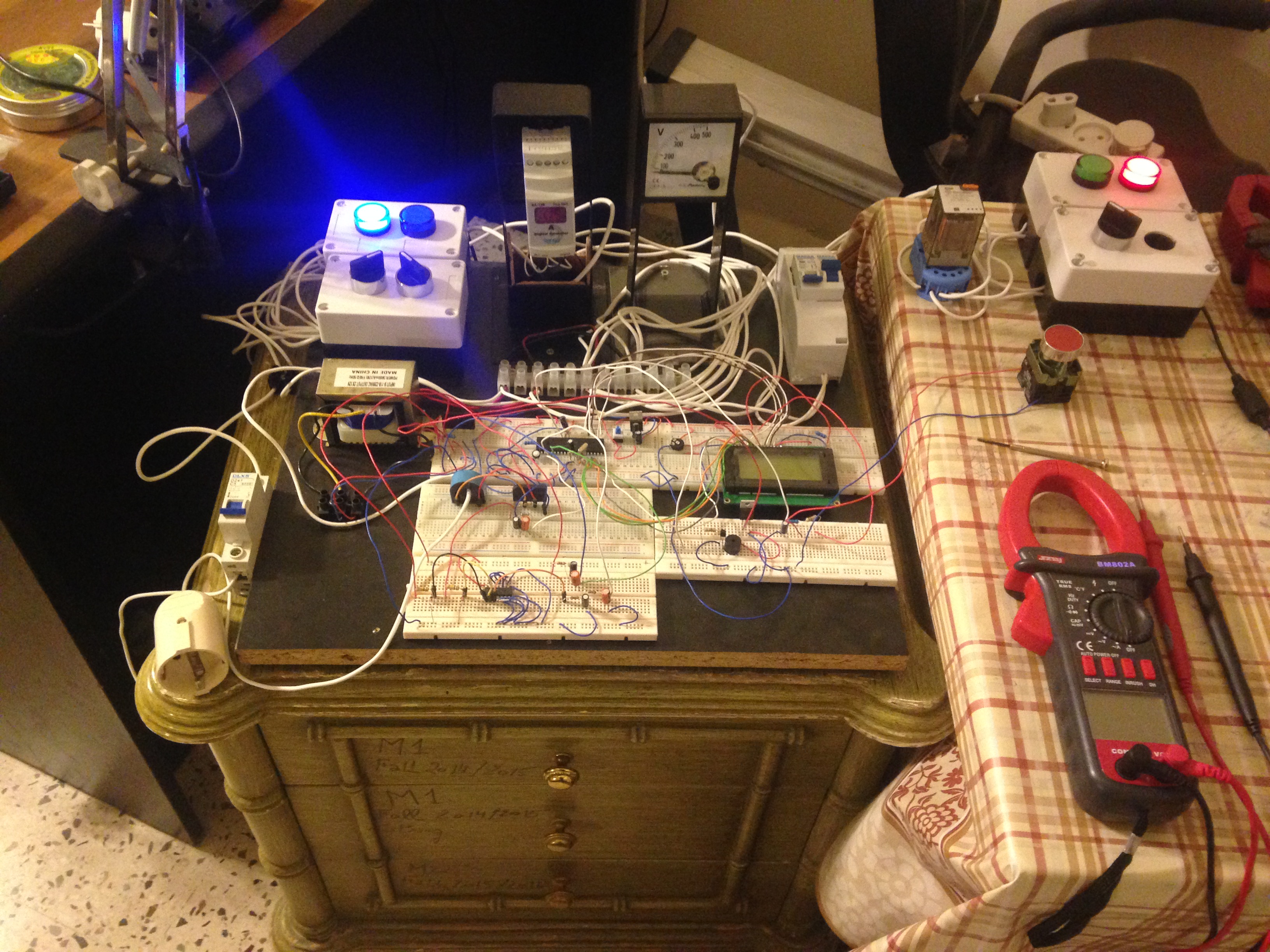
When unplugging the load, either by removing it from socked, or by switching off its MCB, the system behaves as if the user had pressed the push-button.

Thank you

P.s the push-button is rated at 10A, and looks like this one:

https://ar.aliexpress.com/item/Chea...2283684425.html?spm=2114.51010308.4.18.uf0M4j

- - - Updated - - -

Hello,

I've changed the decoupling capacitors value at both VDD & VSS pins from 10nF parallel with two 1uF at each side, to 10nF parallel with 10uF at both sides.

The first time I tried to unplug the load, no re-direction to 'capbankcalc' loop was there (system did not receive it as pressing the pushbutton).

At later tries, with same 10nF parallel with 10uF at both sides, when unplugging the load, the system returned to old behavior as seeing this as pressing the push-button.

Thanks
 

Khaled, is it possible to wire the switch to ground and use a pull-up resistor on PortB.0 instead?

Although it still seems like an electrical problem, maybe reversing the switch signal so it senses the input going low instead of high will help.

Brian.
 
Khaled, is it possible to wire the switch to ground and use a pull-up resistor on PortB.0 instead?

Although it still seems like an electrical problem, maybe reversing the switch signal so it senses the input going low instead of high will help.

Brian.


Hello Brian! How was your meeting?!

I've changed the push-button circuitry from using a pull-down resistor, to a pull-up resistor like the following:


I've used a DVM to test the voltage at the wire heading to PORTB.0, it showed a 4.96VDC when switch was not pressed, and 0V when switch (push-button) is switched. The image of pressing the push-button between VDD and VSS as a short, is maintained by the 10K resistor.


I also changed the ISR code, to detect a Low instead of High:
Code:
isr:
On Low Interrupt
 If INTCON.INT01F = 1 Then
  switch_pressed = 1
  INTCON.INT01F = 0 
 Endif
Resume

The results were:
*Code stopped functioning, as LCD didn't show any output, or showed the first LCDOUT of "Processing..." and got stuck there.


The "On Low Interrupt" caused this dysfunction.

I tried to re-write the Code, by referring to old ISR, as:

Code:
On High Interrupt
 If INTCON.INT01F = 1 Then
  switch_pressed = 1
  INTCON.INT01F = 0 
 Endif
Resume

And by using same pull-up resistor push-button circuit: the code ran great, except that there is always a near 5VDC on PORTB.0 so no interrupt is there, the code gets stuck at where it should be, at 'here' loop, except when disconnecting the load, the code re-directs to 'capbankcalc' , meaning that the switch off of the load, acts as an electrical interrupt.

Thank you

- - - Updated - - -

Added:

Hello,

I think the pull-up push-button with On Low Interrupt can work good, but the problem is with 'setuppic' loop: HEX values within INTCON must be changed such that the clock edge is turned to high
 

Hello,

Using same attached photo, and with the following changes in code:

Code:
setuppic:
TRISB = 0x03
T1CON = 0x24
INTCON = 0x10
INTCON2 = 0xc0
INTCON3 = 0x00
ADCON1 = 0x0c
Enable Low
Return

and for the ISR:

Code:
isr:
On Low Interrupt
	If INTCON.INT0IF = 1 Then
		switch_pressed = 1
		INTCON.INT0IF = 0
	Endif
Resume

The system ran good, but even when push button is pressed, the ISR didn't receive it and furthermore did not set switch_pressed to 1
 

I see the problem. If you change the code back to "On High Interrupt" and "Enable high" it will probably work again.

In the ISR, "high" and "low" refer to the interrupt priority, not the polarity on the interrupt pin. The PORTB.0 interrupt is always high priority so when you changed the code to "Low" the ISR would never be called. It would still generate an interrupt but instead of your ISR it would go to some other routine decided by Oshonsoft which is probably just a "RETFIE - return from interrupt" instruction.

You are right in thinking you have to change the edge that triggers the interrupt so instead of looking for the rising edge when the switch connect the pin to VDD, it looks for the falling edge as it connects it to ground. That means bit 6 of INTCON2 (INTEDG0) needs changing from 1 to 0 so the new value should be 0x80.

The meeting - it went well but 9 hours of travelling for a 2 hour meeting was very tiring!

Brian.
 
Thanks for your reply Brian!!

You mean I still use a pull-up push-button, with On High Interrupt & Enable High but change INTCON2 = 0X80 and see what happens when I disconnect the load?
 

Yes, all I want you to do is reverse the switch wiring so it pulls the pin low when the switch is closed and also change INTCON2 so it looks for the falling edge instead of the rising one. Everything else should be as before. PORTB.0 always triggers a high interrupt but if you don't change INTCON2, the interrupt will be triggered when the switch releases instead of when you press it.

Brian.

Hello Brian,

Done that. Reversed the switch, hardware (attached previously) and within code.
Result: Same.


>>>>>When disconnecting the load, when 'here' loop is acting, the system acts if push-button is pressed.

Problem is still there.

Thank you

- - - Updated - - -

Add current limiting resistors, and de-bouncing capacitor to the new pull-up pusu button then trying again maybe?

- - - Updated - - -

Added:

When you disconnect load manually, from its socket, no spike/interference are there, and code functions as it should be.

only when you turn off the load by turning off its circuit breaker, it produces a spike, and system sees it as pressing the push button.

These results are better than before:

before even if you disconnected load manually out from its socket, system sees it as push button pressing.

Can I consider this level of project as bug-free and move on to next task?


Thank you
 

I think the software is OK. If the circuit breaker 'tricks' the system into thinking the switch was pressed it still points to an electrical issue. I would leave the switch on the ground side of the circuit, it is generally safer to do that because the switch wires do not carry supply voltage. You could filter the switch signal again with the RC network to be doubly sure it isn't picking up interference on the wiring.

The only other way the interference could be getting in is through the power supply itself. You already have the correct decoupling components fitted but it is possible the whole supply, including ground, is carrying a spike. It's difficult to tell which path it travels through but you might be able to try fitting an interference filter in either the power feed to your unit or the power feed to the circit breaker to see if that helps.

Brian.
 
Hello Brian, thanks for replyin! (rap rhyme)

I think the software is OK. If the circuit breaker 'tricks' the system into thinking the switch was pressed it still points to an electrical issue. I would leave the switch on the ground side of the circuit, it is generally safer to do that because the switch wires do not carry supply voltage. You could filter the switch signal again with the RC network to be doubly sure it isn't picking up interference on the wiring.

So you have no problems with the following pull-up push-button circuit, and it is stable upon usage:

https://obrazki.elektroda.pl/4654123600_1460545513.png


If I want to improve it, to make a double security, I can change it to:


And from another side, placing load MCB at GND instead of hot wire.


From another side, and regarding about capacitor bank calculation, I must switch on a capacitor bank with precise parameters, whenever got to 'capbankcalc' function.

I must upgrade pf, from given load, in this case for example, the fan gave around 0.7 LAG as cosine phi value, to a maximum of 0.85.

Assume I know the parameters of capacitor bank, and I only want to switch them using the PIC, after the user has already confirmed to do so by pressing the pull-up push-button:

Is the Sharp S216S02 is able to be considered as a switch instead of Open-Relay Switch to drive in/off capacitor bank?

Plus, what kind of circuitry is needed to be present for electrical safety when dealing with large capacitors? Assuming that the capacitor bank is well driven by PIC, using the Sharp IC stated, when load is disconnected and capacitor is still charged, it can produce a damaging ringing effect, how to be safe with that?


Last point, increasing power factor near unity, is very electrically healthy, it compensates VAR, reduces voltage dips, and so on, but in this case, the resultant cos(phi) is not showing if leading or lagging, due to absence of specific circuits that tells whom crossed first zero, is it voltage or current.

Assuming I will only have loads, with lagging power factor (inductive), I must make closer current and voltage wave forms, as much as possible, this translates by increase of cos(phi) since phi is getting smaller, and cos(phi) is max when phi is zero. To make this closure of V and I wave forms, and since I lags V, the capacitor bank gives VAR so that I wave form can catch up as much as possible V wave form. In case of a leading load, the pf corrector must takes VAR so that I and V get as close as possible together, in this case no capacitor bank is used, instead a choke (reactor) is used. Is this understanding true of false?


Thanks!
 

I'm afraid at my age, emulating a rapper would result in limbs falling off. :sad:

The RC filter was to average the phase pulses so the ADC saw a more stable voltage but for cleaning up a switch signal you don't need such a long time constant. A 1uF capacitor across PORTB.0 and ground should be enough but I would add a 100 Ohm resistor in series with the switch as well. When the switch is closed the voltage from the 10K/100 Ohm divider will still be seen as logic low but the current through the switch contacts as they close will be limited to a safe level. If you directly short out the capacitor with the switch it might cause a spark at the contacts which will reduce its life.

I have no experience with the Sharp device but I'm not sure it would work as intended. What concerns me is the internal zero crossing circuit works only on the voltage across the device so it may not switch the capacitor in at the right time to correct the power factor. In other words it may lock to the voltage phase and not compensate at all. I would ask for advice from others with more experience on that matter. A mechanical relay would certainly work because the capacitor would remain connected through the full AC cycle.

I think you explanation of the power factor correction is right. For the most part you would be connecting capacitors across the AC lines to compensate for the inductive load.
For safety, wire a 100K resistor across each capacitor so it discharges quickly when taken out of circuit. The resistor will have almost zero effect on the measurement but it will safely dissipate any remaining charge on the capacitor within a few seconds.

Brian.
 
A mechanical relay would certainly work because the capacitor would remain connected through the full AC cycle.

I think you explanation of the power factor correction is right. For the most part you would be connecting capacitors across the AC lines to compensate for the inductive load.
For safety, wire a 100K resistor across each capacitor so it discharges quickly when taken out of circuit. The resistor will have almost zero effect on the measurement but it will safely dissipate any remaining charge on the capacitor within a few seconds.

Brian.

Hello Brian, much thanks and respects,

So you were saying that the optimum switch circuit would look like:


And for the capacitor, once determined its parameters (capacitance, rated voltage of operation, ....) I can connect one terminal of it to the load socket, and the other terminal is judged by PIC's switching interface, which is most likely to be an open-relay switch that connect the second terminal to the other side of the load at PIC's order connection/disconnection.

For security, only a short of 100k between cap terminals would disable all kinds of risks


Thank you

- - - Updated - - -

Added:

What is the rated power of the 'bleeding resistor', and are there any solid-state switching method (IC) to connect the cap during the whole AC cycle as open-relay switch does?
 

Hi,

Switch circuit:
Interchange 100R and 10k.

Switch current = 100R current = 5V / 100R = 50mA. Power = 5V × 50mA= 250mW.
10k power is low.
Time constant = R × C = 10k × 1u = 10ms

Klaus

Klaus
 
No, don't interchange the resistors but the 10K should be on the other side of the 100 Ohm resistor. If you short out a capacitor, even a small one like 1uF you get a spark, the 100 Ohm resistor is small enough that it has negligible effect on the output voltage when the switch is closed but large enough to prevent the switch contacts being damaged.

As the switch closes, it is quite normal for the impact of the contacts to make them bounce back, it all to do with the elasticity of the materials. As the contacts bounce the logic level would rise and fall rapidly. The signal is connected to an interrupt input which means it will react to the first transition of the signal from high to low and then ignore any further input until the ISR is finished and the interrupts are enabled again so to some degree, the software 'de-bounces' the signal anyway. The capacitor is there to help filter out rapid signal transitions and to help prevent other signals being picked up on the interrupt pin wiring.

A larger capacitor will make a better filter but it will also introduce an other problem: consider what happens when you turn the PIC supply off. If the switch is open, the capacitor charges up to supply voltage, when the power is turned off, the PIC and any other component on VDD will discharge the supply voltage fairly quickly but the charge on the debounce capacitor can only trickle away slowly through the 10K resistor. This can make PORTB.0 have a higher than VDD voltage on it which although unlikely, can damage it. If you use a larger capacitor, connect a Shottky diode from PORTB.0 to VDD with its cathode end toward VDD. In normal use it will be reverse biased and have no effect but if VDD goes down, it will make a path to safely discharge the capacitor.

The 'bleed' resistors across the capacitors have to withstand the maximum voltage across the capacitor and their power rating should be at least (V*V)/R Watts. That takes into account the worst case of the capacitor being fully charged when it disconnects, in real life the probabiility is the voltage would be lower so there is an even bigger safety margin. Example: if the capacitor disconnected at 220 V RMS peak it would have Sqrt(2)*220 = 315V across it so a 100K resistor would dissipate (315*315)/100,000 = 0.99W. You could use a higher value to reduce the power loss but the capacitor would hold it's charge for a longer, its a compromise between safety and efficiency.

Brian.
 
Did you solve your problem of false interrupts being produced when devices are connected or removed?
 

Khaled, please add these two lines after the "prog_end" label and let me know what number it displays on the bottom line of the LCD. Try it several times and see if the number is different after the false interrupt. It stays in a loop updating the number so it would be useful to know if unplugging the load makes the number change.

Code:
prog_end:
	Lcdcmdout LcdLine4Home
	Lcdout #RCON

	Goto prog_end

Brian.
 
Hello, and thank you all for your replies:

I tried the 'optimum' switch, using 10K pull-up resistor & 100R in series with the PORTB.0 and a 1uF electrolytic capacitor between the 100R and GND:

https://obrazki.elektroda.pl/8254750900_1460670834.png

When disconnecting the load, from its socket, it triggers a false interrupt.
I tried the old simple 10K pull-up alone, and disconnected the load, also a false interrupt had been triggered.


Yesterday, with same code, circuitry, and load as today, I tried the 10K alone with the push-button, and removed the load form its socket, no false interrupt was triggered.

The false interrupt triggering is not continuous or stable, sometimes it occurs, other it don't whether with the 100R and 0.1uF or without them.

The only difference between today and yesterday is the supply voltage:

Yesterday it was over 210VAC today its below 196VAC.

After all, I can make a 'Gosub checkcurrent' procedure, that sees when a 0 is captured on ADC, I go back to initial current loop, this shall fix the false interrupt, and at the same time gives protection such that capacitor is not connected alone with mains rails.


@betwixt:

The only explanation for this, is your conclusion about a spike, (electrical problem). I see when the load is disconnected, the blue light in the below image weakens then strengthen back for a second (the blue light I connected is lighted after a switch that turns on the load, the other switch for the load is the MCB):


Again, the false interrupt could be healed with a check current sub function that re-directs the whole process to the beginning if load is disconnected, and this is good, since a user can unplug the load, and connect another one with different I, P, pf.

For capacitor bank calculation:

First of all, considering the safety circuit to construct, I will wire a 100K cement wire wound resistor of 10W or bigger, I will see what is available. Are there any denials if its power was 50W or even 100W (beside more money payments)?:

**broken link removed**

For capacitor parameters, it first should withstand a voltage of 350VAC.

About its capacitance, first, the inductive load (fan) has a pf of 0.73, let's say I want to improve it to 0.85:

Here is how to get C:

1) Get reactive power of the motor @ uncorrected pf:

Q1 = P * Tan (theta1)

2) Get reactive power of the motor @ corrected pf:

Q2 = P * Tan (cos^-1(0.85))

3) Get Qc rating of the capacitor as: Qc = Q1 - Q2

Since I want to get Xc in order to get C as: C = 1 / 2 * pi * f * Xc

I can get Xc in two methods, one of them depends on load current, the other states that:

Xc = V*V / Qc

Please state if I`m doing any thing wrong. No need for numerical answers at the moment, only procedures.

Let's say the capacitor should be of 680uF at 350VAC, is it preferable to get a single large cap with these parameters, or divide its capacitance by getting 'n' caps in parallel?


Last point, I want to bring a new LCD for the project, and since OshonSoft can maximum comprehend a total of 80 chars on LCD, I thought best way to present data on LCD is to bring one with 20X4 (20 characters, 4 lines, the one I`m working with at the moment is 16X4).

Thanks

- - - Updated - - -

Did you solve your problem of false interrupts being produced when devices are connected or removed?


Hello c_mitra,

No. Not yet.

Thanks
 

My suggestions:

1. Use a pi filter for the PIC power supply pin;

2. Twist the wires that connect to the interrupt pin (may be you are getting interrupts wirelessly)- how long this connection is?

3. Ground the switch body (if it is a big bloke)

Good luck!
 
Hello all,

Using a simple Open-Relay switch, with anti-reverse 1N4007 diode across relay's terminal, I want to connect a capacitor to the inductive load, as soon as the user presses the push-button:

First, cap parameters must be calculated:

Vrating of capacitor must at least exceeds 320VAC.

As for capacitance, the targeted power factor is of 0,85 and I already have the old power factor and its phase.

The Leading VAR that must be supplied by the cap is:

Q = V*I*Tan(theta1 - theta2)

And cap reactance is:

Xc = V*V/Q

Therefore C = 1 / 2 * Pi * 50 * Xc

Once C is got, I get a large capacitor rated ~400VAC and connect one of its terminals directly to one of the load Vsupply terminal.

Its other terminal is connected also to the secons Vsupply terminal of the load, but not directly, using the open relay switch that closes when PIC make decision.

Is it better to get 'n' capacitors with equal capacitance of C/n and connect them in parallel, instead of connecting a single cap with capacitance C?

Also, the bleeding resistor for saftey is of 100K of 10W branched between cap terminals.

Please, any comment? Is this procedure safe to be proto-typed?

Thanks
 

1N400x across the relay COIL, not the terminal (switch) side. It can be any 1N400x or similar diode, the voltage rating is not important as it will never exceed ~0.7V when the diode conducts and the relay coil voltage when not conducting.

The 10W rating of the bleed resistors is far more than you need. What is more important is their voltage rating, most small resistors are rated no higher than 250V so it would be best to use two in series to share the voltage. The resistance isn't critical, it is only to ensure the capacitors discharge when out of circuit for safety reasons. Bear in mind that to charge them to peak voltage you would have to open the relay at the exact instant of the AC peak, the chances of that happening are fairly low and it is far more likely they will have a lower voltage across them. If you use two 100K 1W resistors in series it will be more than adequate and much cheaper/smaller.

Yes, if you need large capacitor values, make it from several smaller value capacitors in parallel.

Brian.
 
Status
Not open for further replies.

Part and Inventory Search

Welcome to EDABoard.com

Sponsor

Back
Top