Continue to Site

Welcome to EDAboard.com

Welcome to our site! EDAboard.com is an international Electronics Discussion Forum focused on EDA software, circuits, schematics, books, theory, papers, asic, pld, 8051, DSP, Network, RF, Analog Design, PCB, Service Manuals... and a whole lot more! To participate you need to register. Registration is free. Click here to register now.

[PIC] Power factor measurement using PIC18f4520

Status
Not open for further replies.
80mS is overkill, most switches will settle in <10mS but how long is needed in the program depends on when the switch is next checked. The debounce is only important if there is a risk of the the input being read more rapidly than the contacts settle and it being seen as in the wrong state during the bounce period.

Khaled, look at table 19-2 on the data sheet, it tells you the bits you have to set in ADCON1 to make the pins analog or digital. They default to analog when the PIC is reset for safety reasons.

Brian.


Hello Brian and thank you!

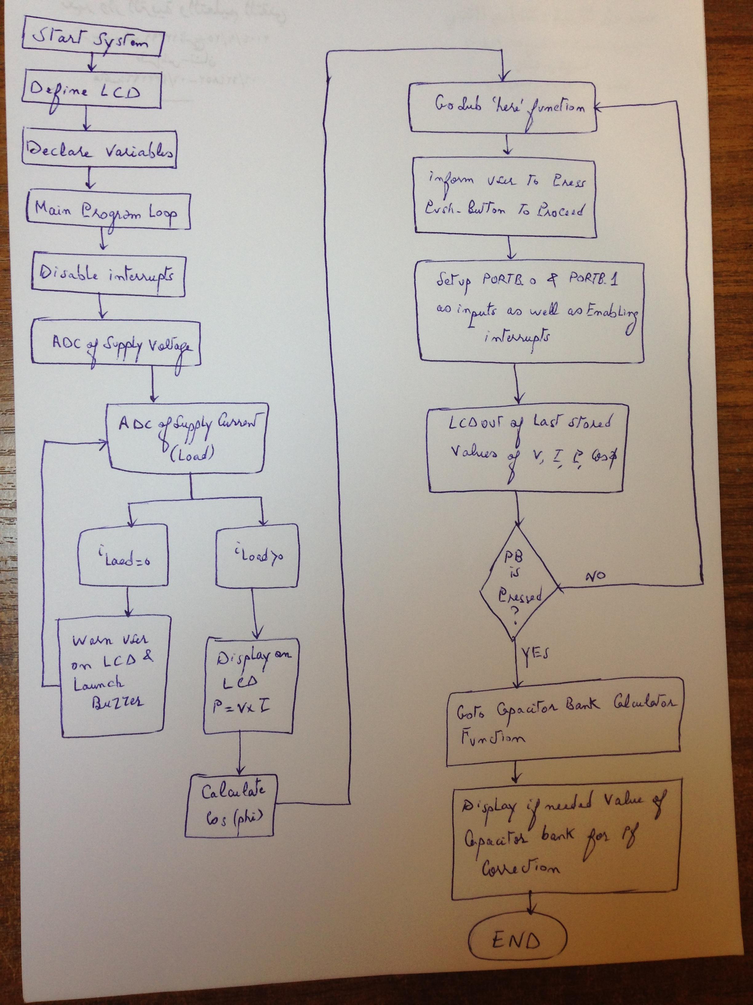
What I intend to is having the response of the system as fast as it can be achieved whenever the user has pressed the push button.

If user presses push then directly go to the destined loop

here is the code:

Code:
Lcdcmdout LcdClear
	Lcdcmdout LcdLine1Home
	Lcdout "Press Red Button"
	Lcdcmdout LcdLine2Home
	Lcdout "To Continue"
	If PORTD.3 = 1 Then //I've added so many fragments of this code, because i want the system to react directly when the user presses the red push button. If I don't do this perhaps the user presses the push button but the system ignores it because it hasn't seen it yet
		Goto capbankcalc
	Else
	WaitMs 1400
	If PORTD.3 = 1 Then //same reason
		Goto capbankcalc
	Endif
	
	Lcdcmdout LcdClear
	Lcdcmdout LcdLine1Home
	Lcdout "Vinput: ", #x, "V"
	If PORTD.3 = 1 Then //same reason
		Goto capbankcalc
	Endif
	Lcdcmdout LcdLine2Home
	Lcdout "I(load)= ", #allcurrent, "A"
	Lcdcmdout LcdLine3Home
	Lcdout "Power: ", #pow, "W"
	If PORTD.3 = 1 Then
		Goto capbankcalc
	Endif
	Lcdcmdout LcdLine4Home
	Lcdout "pf: ", #pf
	If PORTD.3 = 1 Then
		Goto capbankcalc
	Endif
	WaitMs 1000
	If PORTD.3 = 1 Then //same reason
		Goto capbankcalc
	Else
	Goto here
	Endif
	Endif

	
capbankcalc:
Lcdcmdout LcdClear
Lcdout "The input pf"
Lcdcmdout LcdLine2Home
Lcdout "is: ", #pf
If pf > 0.85 Then
	Lcdcmdout LcdLine3Home
	Lcdout "pf is optimal"
	WaitMs 1000
	Goto prog_end
Else
Lcdcmdout LcdLine3Home
Lcdout "Correcting..."
WaitMs 1000
Endif
//to be continued later
prog_end:
End

Perhaps this problem can be solved by making an ISR for the pushbutton?? Whenever pressed directly go to the desired loop, but what I fear of is what if the user presses this button at the beginning of the program, but can this be solved by marking a flag at almost the end of code such that even if the user pressed it, before a flag is marked 1 for example no ISR routine will make effect because its if/else condition were not satisfied?
 

Hi,

Whenever pressed directly go to the desired loop, but what I fear of is what if the user presses this button at the beginning of the program, but can this be solved by marking a flag at almost the end of code such that even if the user pressed it, before a flag is marked 1 for example no ISR routine will make effect because its if/else condition were not satisfied?

My recommendation: Draw a flowchart (only a draft will do) and automatically you will see if there is a problem or not.

Klaus
 
In

Code:
capbankcalc:

function you have a 1 sec delay and that is causing the problem. Remove that delay and debounce the switch and everything will work fine.
 

hello, what about this:

Code:
here:
	intflag = 1
	Lcdcmdout LcdClear
	Lcdcmdout LcdLine1Home
	Lcdout "Press Red Button"
	Lcdcmdout LcdLine2Home
	Lcdout "To Continue"
		
	Lcdcmdout LcdClear
	Lcdcmdout LcdLine1Home
	Lcdout "Vinput: ", #x, "V"
	
	Lcdcmdout LcdLine2Home
	Lcdout "I(load)= ", #allcurrent, "A"
	Lcdcmdout LcdLine3Home
	Lcdout "Power: ", #pow, "W"
	
	Lcdcmdout LcdLine4Home
	Lcdout "pf: ", #pf
	
	WaitMs 1000
	
	Goto here
	Endif
	Endif

	
capbankcalc:
Lcdcmdout LcdClear
Lcdout "The input pf"
Lcdcmdout LcdLine2Home
Lcdout "is: ", #pf
If pf > 0.85 Then
	Lcdcmdout LcdLine3Home
	Lcdout "pf is optimal"
	WaitMs 1000
	Goto prog_end
Else
Lcdcmdout LcdLine3Home
Lcdout "Correcting..."
WaitMs 1000
Endif
prog_end:
End                                               

setuppic:
TRISB = 0x03  'TRISB has bits 0 And 1 As inputs
INTCON = 0x50  'only INT0 and peripheral interrupts enabled
INTCON2 = 0x80  'PORTB pull-ups disabled
INTCON3 = 0x04
Return                                            

On High Interrupt
	Save System
	If intflag = 1 Then
		If PORTB.0 = 1 Then
			Goto capbankcalc
		Endif
	Endif

- - - Updated - - -

I think that the if PORTB.0 = 1 INSIDE THE ISR ROUTINE has no meanings and should be removed because the ISR it self is launched whenever a high voltage on portb.0 is there

please correct any wrong info
thanks

- - - Updated - - -

The aim of this portion of code is that whenever the push button is pushed, go to the function that seeks how to improve pf by adding cap banks:


Code:
here:
	intflag = 1
	Lcdcmdout LcdClear
	Lcdcmdout LcdLine1Home
	Lcdout "Press Red Button"
	Lcdcmdout LcdLine2Home
	Lcdout "To Continue"
	WaitMs 1000
		
	Lcdcmdout LcdClear
	Lcdcmdout LcdLine1Home
	Lcdout "Vinput: ", #x, "V"
	
	Lcdcmdout LcdLine2Home
	Lcdout "I(load)= ", #allcurrent, "A"
	Lcdcmdout LcdLine3Home
	Lcdout "Power: ", #pow, "W"
	
	Lcdcmdout LcdLine4Home
	Lcdout "pf: ", #pf
	
	WaitMs 1000
	
	Goto here


capbankcalc:
Lcdcmdout LcdClear
Lcdout "The input pf"
Lcdcmdout LcdLine2Home
Lcdout "is: ", #pf
If pf > 0.85 Then
	Lcdcmdout LcdLine3Home
	Lcdout "pf is optimal"
	WaitMs 1000
	Goto prog_end
Else
Lcdcmdout LcdLine3Home
Lcdout "Correcting..."
WaitMs 1000
Endif
prog_end:
End                                               

setuppic:
TRISB = 0x03  'TRISB has bits 0 And 1 As inputs
INTCON = 0x50  'only INT0 and peripheral interrupts enabled
INTCON2 = 0x80  'PORTB pull-ups disabled
INTCON3 = 0x04
Return                                            

On High Interrupt
	Save System
	If intflag = 1 Then
			Goto capbankcalc
	Endif
			
end_of_isr:
Resume

When all V, I , P , pf are calculated I've made a function called 'here' that the user cannot escape unless he pressed the push button.

When he presses the push button (pull-down resistor) same as I attached, a high interrupt is triggered at PORTB.0, that directs the user to another loop 'capbankcalc'

but this is not working
Thanks

- - - Updated - - -

I've enable global interrupts by:

INTCON.GIE = 1

and made Enable High in the main function

The following is the code for pic setup and interrupt:


Code:
setuppic:
TRISB = 0x03
INTCON = 0x10
INTCON2 = 0xe0
INTCON3 = 0x08
ADCON1 = 0x0c
Return                                            
isr:
On High Interrupt
	
	If intflag = 1 Then
			Goto capbankcalc
	Endif
			
end_of_isr:
Resume

the intflag is set to zero at the beginning of the code, but re-set to 1 in 'here' loop:

Code:
here:
	intflag = 1
	Lcdcmdout LcdClear
	Lcdcmdout LcdLine1Home
	Lcdout "Press Red Button"
	Lcdcmdout LcdLine2Home
	Lcdout "To Continue"
	WaitMs 1000
		
	Lcdcmdout LcdClear
	Lcdcmdout LcdLine1Home
	Lcdout "Vinput: ", #x, "V"
	
	Lcdcmdout LcdLine2Home
	Lcdout "I(load)= ", #allcurrent, "A"
	Lcdcmdout LcdLine3Home
	Lcdout "Power: ", #pow, "W"
	
	Lcdcmdout LcdLine4Home
	Lcdout "pf: ", #pf
	
	WaitMs 1000
	
	Goto here

The push button already worked, with the other than interrupt code form. It is NO. and has not hardware problem

Any Suggestions
thanks
 

It is a bad program when you put an unconditional delay of 1 sec. within the ISR. You can perhaps move the delay outside the ISR. Instead of waiting for the godot, you can check the status of the LCD in a loop till it is ready and that is the recommended way.
 

Hello and thank you,


I`ve fixed the problem of push button, and it operates under interrupt and it only functions when intflag is equal to one.

It takes immediate action right after a single press of it.

The new problem is, that if intflag is not set to 1, no interrupt function would take place, but the whole code gets stuck at where it was.

How to fix this? here is the code:

Code:
here:
	intflag = 1
	Lcdcmdout LcdClear
	Lcdcmdout LcdLine1Home
	Lcdout "Press Red Button"
	Lcdcmdout LcdLine2Home
	Lcdout "To Continue"
	WaitMs 1000
		
	Lcdcmdout LcdClear
	Lcdcmdout LcdLine1Home
	Lcdout "Vinput: ", #x, "V"
	
	Lcdcmdout LcdLine2Home
	Lcdout "I(load)= ", #allcurrent, "A"
	Lcdcmdout LcdLine3Home
	Lcdout "Power: ", #pow, "W"
	
	Lcdcmdout LcdLine4Home
	Lcdout "pf: ", #pf
	
	WaitMs 1000
	
	Goto here


capbankcalc:
Lcdcmdout LcdClear
Lcdout "The input pf"
Lcdcmdout LcdLine2Home
Lcdout "is: ", #pf
If pf > 0.85 Then
	Lcdcmdout LcdLine3Home
	Lcdout "pf is optimal"
	WaitMs 1000
	Goto prog_end
Else
Lcdcmdout LcdLine3Home
Lcdout "Correcting..."
WaitMs 1000
Endif
prog_end:
End                                               


isr:
On High Interrupt
	If INTCON.INT0IF = 1 Then
		If intflag = 1 Then
			Goto capbankcalc
			INTCON.INT0IF = 0
	Endif
	Else
		Resume
	Endif

The problem is if the user presses the push button, before 'here' function took place, that means before the intflag is set to 1

- - - Updated - - -

Also there is a physical problem with HD74S86: when connected to circuit even if from another supply (7805 voltage regulator fed by a 9V zinc battery) the LCD don't show a word. If you deplug it from its source, the LCD shows back again characters as supposed, why?

- - - Updated - - -

Here it is in another way:

1) The interrupt code for the push button is running great, but the problem is when pressing it when intflag is not set to one, like if pressed at the beginning of the project, the code stops at the last place it was executing


2) Sometimes when placing the XOR circuit that serves for power factor measurement in the circuit, the LCD stop functioning by not showing any character, this problem is solved by un plugging the XOR from the total circuit


Thanks
 

Isn't BASIC the most wonderful tangle of criss-crossed code!

The 74S86 problem can only be the current it draws, no matter what it's output voltage is, the circuit should still function. The 'S' series of 74 logic gates is for use when extremely short propagation delays are needed but the penalty is high current consumption. A 9V zinc battery may not be good enough to power even a single 74S86 as it could drag the 9V low enough that the 7805 regulator stopped working. You need at least 8V available at the regulator input pin and a 75mA load may be enough to pull the battery below 8V. If you can change it to a 74AC or 74ACT device it will draw far less current and also give better output voltage range. If you have to keep using the 74S86 try tieing its unused input pins to ground to ensure it remains stable.

The software problem is to do with Oshonsoft again. It only allows one 'Resume' statement in an ISR and you have code that may never return from the ISR if the innermost 'If' statement returns false. It is also very bad practice to use delays inside an ISR as it blocks further interrupts occuring.

See if you can restructure the code so the interrupt sets a flag then immediately returns ("resumes"). Then check the flag in your main loop of code and execute 'capbankcalc' if the flag is set, resetting it afterwards so it is ready for next time the switch is pressed.

Brian.
 
Hello

@betwixt

I've tried the following code:

Code:
isr:
On High Interrupt
	If INTCON.INT0IF = 1 Then
		If intflag = 1 Then
			Goto capbankcalc
			INTCON.INT0IF = 0
	Else
			Goto end_of_isr
			INTCON.INT0IF = 0
		
	Endif
	Endif
end_of_isr:
Resume

Such that, if the button is pressed, but the intflag is not yet been set to 1 then go to the end of ISR routine, that reveals an Resume

But it also did not work!

I could have done it with a flag setting within the interrupt routine, but i want to enter the capbankcalc loop only when the button is pressed.

Any suggestions?

Thank you

- - - Updated - - -

What if I Disable High in the main program loop, and only enable it in the here function where the intflag is set to one?
 

Hi

Can the instructions immediately after the "goto" lines ever be processed?

Klaus
 

No they can't - but even worse, after "Goto capbankcalc" the program reaches the end, it never even gets to clear the interrupt.

Khaled, I'm not sure it will fix your problem but instead of "Goto" try using "Gosub" and at the end of the "capbankcalc" routine, use "Return" instead of "End". It will return the control to the ISR where it was called from instead of "falling off the end of the program". I still think the answer is to let the ISR notify the main loop that the button was pressed but do all the decision making in the main loop and not the ISR.

Brian.
 
Hello,

@betwixt

It worked, such that only if the user presses the push-button it redirects to capbankcalc loop, by disabling all interrupts, except just before the 'here' function.

If a user presses the push-button before asked from LCD, nothing happens and program functions as it should be, only when a "Press Push-Button to continue" is there on LCD, its press is accepted.

Still, I've used Goto capbankcalc function, in the ISR and it is also working good for the moment.

Here is a brief explanations for what I've done to correct push-button issue:
1. Placed a Disable High in the main program loop, and Enable high right after 'here' loop. [DIDN'T work]
2. Deleted Disable High in the main program loop, and Enable high is now right before 'here' loop. [DIDN'T work]
3. Placed these right before 'here' loop, and made Enable high within this loop:
Code:
TRISB = 0x03
    T1CON = 0x24
    INTCON = 0x10
    INTCON2 = 0xe0
    INTCON3 = 0x48
    ADCON1 = 0x0f
[It worked!]

I've recently got the 74HC86N used as XOR gate, I will connect it instead of 'S' series of it, and feedback with results.


Too many thanks!
 

Hello,

I`ve connected the 74HC86N instead of HD74S86 using same connections.

Following are the results:

1. When fed the new IC of XOR (74HC86) from PIC's 5VDC rails: The PIC circuit as well as the LCD continued to function normally. This new IC does not depend too much current as 74S86 that stops PIC as well as LCD from proper functioning.

2. When Connected a 200W resistive bulb, it showed a phase of 0.000 thereby a cos of 1. This was not shown by the old 74S86, it showed values from 0.889 to 0.933 for this same load.

3. When Connected the 60W fan, it showed a phase of 639.74 SAME when I've connected a 15W LED AC bulb

4. I've kept the "fudgefactor" same as it was for the old 74S86: When there wasn't any load, it showed no load.

5. Sometimes the code functions well, and shows "Press push button to continue" and uses interrupt that once pressed re-direct code to 'capbankcalc'.
Other times, the code get stuck at last position when it was before the 'here' loop, by showing resultant pf only *but* if you press the push button it will also go to 'capbankcalc' but without previously showing on LCD that press push button
Other times, when I switch the load off (especially if it was the resistive one) it automatically goes to 'capbankcalc'

6. When I tried to get proper value for phase, as referred to p_divider in previous posts, I thought that the fan should have a phase angle near 43 degrees more or less.
So: I divided the phase angle resulting by 14.689 (since 369.74/14.689 = 43) to get a pf of around 0.7.
When done and burned to code onto the PIC, I saw a phase angle of 68.8 for both LED Bulb and 60W fan, that means the original phase before dividing it was 68.8 * 14.689 = 1010.632 instead of 639.74

The following is the BASIC code

Code:
ASM:        org 0x800
Define LCD_LINES = 4
Define LCD_CHARS = 16
Define LCD_BITS = 8  'allowed values are 4 and 8 - the number of data interface lines
Define LCD_DREG = PORTC
Define LCD_DBIT = 0  '0 or 4 for 4-bit interface, ignored for 8-bit interface
Define LCD_RSREG = PORTD
Define LCD_RSBIT = 0
Define LCD_EREG = PORTD
Define LCD_EBIT = 2
Define LCD_RWREG = PORTD  'set to 0 if not used, 0 is default
Define LCD_RWBIT = 1  'set to 0 if not used, 0 is default
Define LCD_COMMANDUS = 2000  'delay after LCDCMDOUT, default value is 5000
Define LCD_DATAUS = 100  'delay after LCDOUT, default value is 100
Define LCD_INITMS = 100  'delay used by LCDINIT, default value is 100
Define ADC_SAMPLEUS = 255

Lcdinit 0  'initialize LCD module; cursor is blinking


Dim volt As Word
Dim x As Single
Dim current As Word
Dim y As Single
Dim zz As Single
Dim pow As Single
Dim phase As Word
Dim phasean As Single
Dim currentan As Single
Dim currentan2 As Single
Dim allcurrent As Single
Dim flag As Word
Dim fudgefactor As Single
Dim phasedeg As Single
Dim pf As Single
Dim intflag As Byte

Dim vcounter As Word
Dim icounter As Word
Dim pcounter As Word
icounter = 30
vcounter = 30
pcounter = 5
intflag = 0
x = 0
y = 0
zz = 0
pf = 0
fudgefactor = 28
phase = 0
phasean = 0


main:
'Disable High
Lcdcmdout LcdClear
Lcdout "Processing..."
WaitMs 300
Lcdcmdout LcdLine2Home
Lcdout "Testing System"
WaitMs 300
Lcdcmdout LcdLine3Home
Lcdout "Checking Inputs"

While vcounter > 0
Adcin 3, volt

x = x + volt
vcounter = vcounter - 1
volt = 0
Wend

x = x / 30
x = x * 5 / 1024
x = x * (1510 / 510)
x = x + 0.5
x = x * 16.30

WaitMs 5000

Lcdcmdout LcdClear
Lcdout "Vinput: ", #x, "V"

currentloop:
While icounter > 0
Adcin 1, current
   
    y = y + current
    icounter = icounter - 1
        current = 0
    Wend

    y = y / 30
    WaitMs 2000
   
    If fudgefactor > y Then
        Goto noload
    Endif
   
    currentan = y * 5 / 1024


If y = 0 Then
noload:
    flag = 0
    Lcdcmdout LcdLine2Home
    Lcdout "I: 0 A"
    WaitMs 800
    Lcdcmdout LcdLine3Home
    Lcdout "Power = 0W"
    WaitMs 800
    Lcdcmdout LcdLine4Home
    Lcdout "Phase: NO LOAD"
    WaitMs 800
    Goto prog_end
Else
    flag = 1
    currentan2 = currentan + 0.063
    allcurrent = currentan2 * 0.2
Lcdcmdout LcdLine2Home
Lcdout "I(load)= ", #allcurrent, "A"
Endif

WaitMs 1000
       
If flag = 1 Then
    Lcdcmdout LcdLine3Home
    pow = allcurrent * x
    Lcdout "Power: ", #pow, "W"
    WaitMs 1000
   
    Lcdcmdout LcdLine4Home
    Lcdout "Calculating pf.."
    WaitMs 8000

    Adcin 2, phase
   
   
    Lcdcmdout LcdLine4Clear
    Lcdcmdout LcdLine4Home
    phasean = phase / 14.689
    Lcdout "Phase: ", #phasean
    WaitMs 4000
    phasedeg = phasean * 0.01745329
    Lcdcmdout LcdLine4Clear
    pf = Cos(phasedeg)
    Lcdout "pf: ", #pf
    WaitMs 1000
    Endif
    Gosub setuppic


here:
   
    Lcdcmdout LcdClear
    Lcdcmdout LcdLine1Home
    Lcdout "Press Red Button"
    Lcdcmdout LcdLine2Home
    Lcdout "To Continue"
    WaitMs 1000
       
    Lcdcmdout LcdClear
    Lcdcmdout LcdLine1Home
    Lcdout "Vinput: ", #x, "V"
   
    Lcdcmdout LcdLine2Home
    Lcdout "I(load)= ", #allcurrent, "A"
    Lcdcmdout LcdLine3Home
    Lcdout "Power: ", #pow, "W"
   
    Lcdcmdout LcdLine4Home
    Lcdout "pf: ", #pf
   
    WaitMs 1000
   
    Goto here


capbankcalc:
Lcdcmdout LcdClear
Lcdout "The input pf"
Lcdcmdout LcdLine2Home
Lcdout "is: ", #pf
If pf > 0.85 Then
    Lcdcmdout LcdLine3Home
    Lcdout "pf is optimal"
    WaitMs 1000
    Goto prog_end
Else
Lcdcmdout LcdLine3Home
Lcdout "Correcting..."
WaitMs 1000
Endif
prog_end:
End  
                                            
setuppic:
    TRISB = 0x03
    T1CON = 0x24
    INTCON = 0x10
    INTCON2 = 0xe0
    INTCON3 = 0x48
    ADCON1 = 0x0f
    Enable High
Return

isr:
On High Interrupt
    If INTCON.INT0IF = 1 Then
            INTCON.INT0IF = 0
            Goto capbankcalc
    Else
            Resume
    Endif

Here are my questions:
1. Is the 60W fan have really the same power factor of 15W LED bulb? :lol:
2. The output of 74HC86 is was better than the 74LS86, but how to fix its output? Should I also tie its unused pins to ground?
3. Why did the interrupt of push-button when using 74LS86 was previously solved, and only when asked to press the button, the code immediately responds by going to the desired 'capbankcalc' loop, but when changed to 74HC86 The interrupt problem re-appeared?


Thank you
 

Hi,

Should I also tie its unused pins to ground?
Input pins!
Generally...with all IC's you use in future: Don't ever let inputs floating.
This means you need to read the datasheet carefully. Some inputs have pullups/pulldowns/or other circuitry to prevent the pin from floating. Then you don't tneed to connect anything. With all other unused input pins: tie them to valid levels.
In the very most cases a 100k won't influence the function.
Don't forget input pins with connectors in the signal line. They may eventually be unconnected...and thus floating.

Klaus
 

Here are my questions:
1. Is the 60W fan have really the same power factor of 15W LED bulb?
2. The output of 74HC86 is was better than the 74LS86, but how to fix its output? Should I also tie its unused pins to ground?
3. Why did the interrupt of push-button when using 74LS86 was previously solved, and only when asked to press the button, the code immediately responds by going to the desired 'capbankcalc' loop, but when changed to 74HC86 The interrupt problem re-appeared?

1. Possibly, a single LED runs from DC and is relatively unreactive, it appears like a resistor to the power source but an AC 220V LED lamp will have a small switch mode power supply inside it - or in the case of some cheap types, a capacitive voltage dropper - so their power factor could be almost anything.

2. Yes, the input pins draw almost no current so they tend to 'float' at whatever level they pick up from nearby static charges or capacitive coupling from nearby wiring. A floating input will still be seen by the internal circuits as a valid logic level so you would get random changes in the output state of the gate. If you tie them to ground or even just connect them to ground through a resistor it will ensure they are always seen as a steady logic state. The other change you will see with the HC (or any CMOS type) is a low output nearer to 0V and a high output nearer to 5V, the 'S' version is designed for high speed but it's output voltages may not reach the full range of 0V to 5V, remember it is the average voltage you are measuring to determine the phase shift so if it only went down to say 0.2V, that would be the lowest possible input voltage the ADC would see. You have removed any residual voltage with the 'fudge factor' but if the residual is now changed, the fudge factor may need adjusting.

3. I will have to look at the code more closely. Changing the IC should not alter the program flow in any way. I'll get back to you later on this as I have urgent work to do right now.

Brian.
 
I've had a quick look at the code and there is a problem with the flow.

Minor problem:
set up the PIC before using it, move the "gosub setuppic" to the top of the program just after main:

Major problem:
The stack is out of balance. Consider what happens when the ISR is called, you check if it was from the switch, clear the interrupt flag then jump to 'capbankcalc' without returning from the ISR. It leaves the return address from the ISR on the stack and also leaves the global interrupt bit disabled. There is no way it can reach the 'Resume' statement to finish the ISR properly.

I suggest a flow chart is drawn so you can see all the possible paths the program should take and ensure you never leave a subroutine or ISR without passing its 'Return' or 'Resume' first.

To check if I'm right with the ISR code, add another variable called 'switch_pressed' then change the ISR to:
Code:
isr:
On High Interrupt
    If INTCON.INT0IF = 1 Then
        INTCON.INT0IF = 0
        switch_pressed = 1
    Endif
Resume

Then in the main loop add
Code:
     If switch_pressed = 1 Then
        switch_pressed = 0
        Gosub capbankcalc
    Endif

And finally add "Return" at the end of the capbankcalc routine.

Brian.
 
Thank you Brian!

Here is the flowchart:
[P.s There still other 'flows' that must be taken into consideration, the following flowchart is for what's done at this level]:


About changing the ISR in adding a new 'switch_pressed' variable: wouldn't this make forces the code to immediately go to 'capbankcalc' function whenever the push button is switched?

Away from interrupt problem, I thought to add a buzzer, such that if system is ON, and NO LOAD is connected, launch a buzzer using ULN2003 and flash "CONNECT LOAD" on LCD.

Here's its code:

Code:
currentloop:
y = 0
While icounter > 0
Adcin 1, current
   
    y = y + current
    icounter = icounter - 1
        current = 0
    Wend

    y = y / 30
    WaitMs 2000
   
    If fudgefactor > y Then
        Goto noload
    Endif
   
    currentan = y * 5 / 1024


If y = 0 Then
noload:
    While y = 0
   
    flag = 0
    Lcdcmdout LcdLine2Home
    Lcdout "I: 0 A"
    WaitMs 800
    Lcdcmdout LcdLine3Home
    Lcdout "Power = 0W"
    WaitMs 800
    Lcdcmdout LcdLine4Home
    Lcdout "CONNECT LOAD"
    WaitMs 800
    Lcdcmdout LcdLine4Clear
    [I]//switch on buzzer using ULN2003[/I]
    Adcin 1, curtest
    y = curtest
    If y > 0 Then
        Goto currentloop
    Endif
   
    Wend
Else
    flag = 1
    currentan2 = currentan + 0.063
    allcurrent = currentan2 * 0.2
Lcdcmdout LcdLine2Clear
Lcdcmdout LcdLine3Clear
Lcdcmdout LcdLine4Clear
Lcdcmdout LcdLine2Home
Lcdout "I(load)= ", #allcurrent, "A"
Endif

WaitMs 1000
       
If flag = 1 Then
    Lcdcmdout LcdLine3Home
    pow = allcurrent * x
    Lcdout "Power: ", #pow, "W"
    WaitMs 1000
   
    Lcdcmdout LcdLine4Home
    Lcdout "Calculating pf.."
    WaitMs 8000

    Adcin 2, phase
   
   
    Lcdcmdout LcdLine4Clear
    Lcdcmdout LcdLine4Home
    phasean = phase / 14.869
    phasean = phasean / 1.6
    Lcdout "Phase: ", #phasean
    WaitMs 4000
    phasedeg = phasean * 0.01745329
    Lcdcmdout LcdLine4Clear
    pf = Cos(phasedeg)
    Lcdout "pf: ", #pf
    WaitMs 1000
    Endif
    Gosub here

According to your reply, of my first project posted here, I used to use an Open-Relay Switch to turn on/off loads, and you advised me to use ULN2003:


Here's what a ULN2003 circuit should be, according to one of your old posts:


Your instructions in circuitry connection, coincide with alexan_e diagram:


So for a 12V piezo buzzer, the connection would be like:


This is to turn HIGH whenever load is disconnected.

Do you have any concerns about ULN2003 circuitry? I also have a problem for 'no load' coding, what I want is, to flash CONNECT LOAD, and launch buzzer for 3 sec ON, 5 sec OFF, until user connects load, it automatically turns LOW buzzer, and go to ADC measurement for load current, but using the code I wrote (bad code) even if user re-plugs the load, the code is still stuck at "CONNECT LOAD" LCD statement.


Thanks
 

About changing the ISR in adding a new 'switch_pressed' variable: wouldn't this make forces the code to immediately go to 'capbankcalc' function whenever the push button is switched?

Yes, but you can always control whether the switch is active or not by 'And'ing with another condition, for example:
Code:
    If switch_pressed = 1 And time_to_do_something = 1 Then
The important thing is the ISR exits through a resume instruction and doesn't divert the program flow somewhere else. The 'Resume' instruction restores saved copies of some of the registers and turns the global interrupts back on again so if you don't execute it, there will be no more interrupts.

The ULN 2003 circuit will not work as shown I'm afraid. All the ULN2003 (and ULN2803) has inside it is a bank of transistors and some protection diodes, the internal circuit is duplicated 7 times (8 for the ULN2803) only for convenience. With only one buzzer as the load, you could use a single transistor if you wanted to, emitter to ground, base to the port pin through a 2.2K resistor and collector to the buzzer then 12V. There are two problems withthe design you show, the first is that no pull-up resistor is needed because the PIC can already drve the ULN2003 directly and in any case it already has internal bias resistors, the second is the buzzer will probably work all the time because there is a path for current to flow through it even if the input to the ULN2003 is low. The problem is caused by the protection diode in the ULN output pin, there is a diode from each output and they are all connected to the 'COM' pin. As 'COM' is shown connected to +5V, there is a path from 12V, through the buzzer then the diode to the 5V rail which leaves ~7V across the buzzer when you really want no voltage across it at all. If you stay withthe ULN2003, remove R1 and connect the COM pin to +12V instead, that will make it work.

I'll take a close look at your flow chart later and see how it corresponds to your code.

Brian.
 
Thank you Brian!!

The 12V that I intend to feed the buzzer from, is the output of the bridge rectifier after the 220/12VAC. Since the supply voltage can reach a 230VAC, the secondary of the transformer can reach to almost 14VDC.

What is the voltage regulator name, that could output a pure DC voltage of 12V, even if its supply is not +2V bigger than the output voltage, like the LM78 series?
 

Hi

A rectified and capacitor filtered 12 V AC signal can reach up to 17V DC. (12V x 1.414 ) ... subtract about 1.4V for full bridge rectifier.
So you should rather expect up to 20V DC.

Klaus
 
Status
Not open for further replies.

Part and Inventory Search

Welcome to EDABoard.com

Sponsor

Back
Top