DasPreetam
Advanced Member level 4
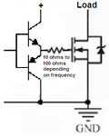
Mosfets without a 100 ohm resistor results in a simulation error. (Wouldn't they burn out due to excessive current without the resistor ?) How to determine how much power will the mosfets deliver ?
In India, we have 230V mains. If the mosfets are producing 26V, then how come the output be 92V ?
Your Mosfets without the 100 ohm resistors produce a peak-to-peak output of about 26V then the 20:1 transformer produces an RMS output voltage of only 92V instead of 120V and the voltage will drop as the battery voltage runs down.
In India, we have 230V mains. If the mosfets are producing 26V, then how come the output be 92V ?