Continue to Site

Welcome to EDAboard.com

Welcome to our site! EDAboard.com is an international Electronics Discussion Forum focused on EDA software, circuits, schematics, books, theory, papers, asic, pld, 8051, DSP, Network, RF, Analog Design, PCB, Service Manuals... and a whole lot more! To participate you need to register. Registration is free. Click here to register now.

Pure Sine Wave Power Inverter

Status
Not open for further replies.

DasPreetam

Advanced Member level 4
Joined
Jan 5, 2014
Messages
100
Helped
2
Reputation
4
Reaction score
2
Trophy points
18
Activity points
755
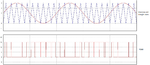
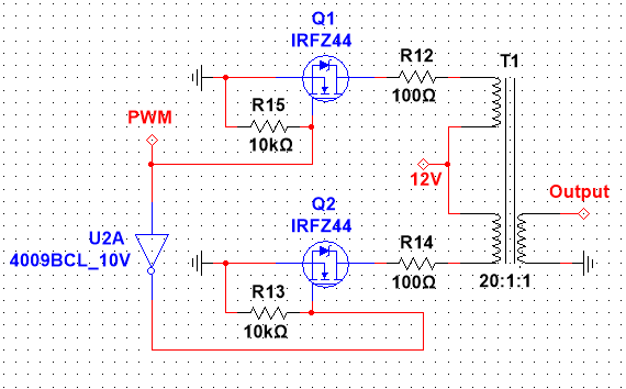
I'm trying to design a DC-AC Pure sine wave power inverter which will take 12 V DC from a battery and Provide a 220 Vrms, 50Hz sine wave output. I've seen many references, but most of them are either square wave or modified square wave.

I've designed a bubba oscillator using LM348 which produces a 50Hz sine wave. But it's amplitude is only 1Vpk. If I connect it directly to a step-up transformer will it work ?

Also, I have another question. In multisim, I'm giving a Vcc/2 offset to the non-inverting terminal of the op-amp. How can I achieve this in real-life ?

The transformer in multisim is stepping up the output along with DC offset... How's that possible ? I thought that the transformer will only step up the AC component !
 

To get Vcc/2 in real life you string two 1k resistors in series across the Vcc rail to earth and take you input to the centre tap.
Transformers only step up AC. I would throw away your copy of Multisim. 1V AC can be stepped up in a transformer, but to start with 1V from an oscillator will only result in micro watts of power is this what you want?
Frank
 

For an inverter "Pure sine wave" is a marketing "spec". No one inverter have such output wave; you may try to be closer to such wave with various tips design and filters.
A class A amplifier may be compliant with such "spec" but even such device in real life have some THD, so it's not "Pure sine wave"...
 

A pure sinewave inverter uses pulse-width-modulation to make a sinewave with hundreds of pulses per cycle. The output Mosfets turn on completely and turn off completely for each pulse so that they waste very little power making heat. A simple filter at the output removes the switching frequency. Because the switching frequency is hundreds of kHz then the stepup transformer is small with a ferrite core.

A linear power amplifier is NEVER used in an inverter because it wastes 60% of the power from the battery making heat.
 
Okay so that's the key ! Okay suppose I'm getting the sine wave, and I make another triangle wave generator of say about 10 KHz, then feed both the outputs to a comparator which drives the mosfet to the output. Is m theory right ? Or am I making some mistake ?

I would throw away your copy of Multisim
What simulator do you suggest ?

Also, I noticed the sine wave oscillates between 6-12V then 6-0V (at the first stage of the oscillator), its not going to the negative voltage, so how can it be ac. Suppose at the starting instant, the instantaneous voltage is 6V, so the transformer is stepping it up. At some other instant, suppose the the instantaneous voltage is 1V, so the transformer is stepping up that too.

In real life, how can I get the negative cycle ?
 

Use a 24V center-tapped transformer with its center-tap is connected to +12V. Each end is driven to ground by an N-channel Mosfet. One Mosfet has its gate PWM signal inverted from the other Mosfet. When one end goes to ground then the transformer action drives the other end to +24V.

The output AC voltage will drop when loaded so a low frequency feedback arrangement must be used for voltage regulation.
 
.............................................
The transformer in multisim is stepping up the output along with DC offset... How's that possible ? I thought that the transformer will only step up the AC component !
How many cycles are you simulating? What is the output load?

Try simulating many cycles into a 1kΩ load and see if it looks different.
 

Use a 24V center-tapped transformer with its center-tap is connected to +12V. Each end is driven to ground by an N-channel Mosfet. One Mosfet has its gate PWM signal inverted from the other Mosfet. When one end goes to ground then the transformer action drives the other end to +24V.

That went above my head, can you please give some reference circuits ?
 

That went above my head, can you please give some reference circuits ?
I am sorry that I do not speak in your language. You must understand how a simple center-tapped transformer makes a full waveform on its secondary.

Look in Google Images for Pure Sinewave Inverter and you will find hundreds of schematics.
 

Okay is this circuit right ?


Also, what are the advantages of a triangle wave over square wave as carrier signal ?
 

Okay is this circuit right ?
No.
You cannot use old-fashioned TTL (74xx series) logic to drive most Mosfets. The minimum output high voltage of the 7404 and for most TTL logic is only +2.4V. The 2N6755 Mosfet barely turns on with a gate-source voltage of +5V and needs +10V to fully turn on as shown in its datasheet.
A "logic-level" Mosfet needs a gate-source voltage of +4.5V to +5V to fully turn on but that is from Cmos logic, not from old-fashioned TTL logic.

Also, what are the advantages of a triangle wave over square wave as carrier signal ?
Frequently PWM is made by using a low frequency sinewave, a high frequency triangle wave and a comparator. Then the output has variable width pulses that quickly switch high and low. The high frequency cannot be a squarewave.
 

How much power can these "logic level" mosfets handle ? I will use a cmos NOT gate.

Frequently PWM is made by using a low frequency sinewave, a high frequency triangle wave and a comparator. Then the output has variable width pulses that quickly switch high and low. The high frequency cannot be a squarewave.

That's my question. Why we can't use square wave of high frequency ? Is it because of the distortion of square wave at high frequencies ?
 

Making PWM needs a low frequency sinewave and a high frequency ramp. A triangle wave or a sawtooth wave is a ramp. A squarewave is not a ramp.

Draw the waveforms on paper and use your brain to be the comparator and you will see that the ramp makes PWM and the squarewave does not.
 

Attachments

  • making PWM.png
    making PWM.png
    354 KB · Views: 112

Keep in mind the source impedance out of your inverter is N squared times your input source impedance, and you want this as low as possible for good load regulation. ( Source/Load determines error)


Using a centre tap 12Vdc to 220Vac you have 220Vac/24Vdc or a turns ratio near 10:1 with a centre tap. So output impedance will be at least 100x bigger than source.

The 2N6755 is an old part with 250 milliohm for RdsON, so output impedance will be at least 25 Ohms.

Consider searching for parts with <50 milliohm or much less than the winding resistance of your transformer primary.

Many distributor sites have search filters for these parameters. It always good to have >30% extra margin for current and low ON resistance after worst case thermal effects are considered.
 

@Audioguru : Okay now I get it. Can you give some common logic level mosfet names ? I'm having a hard time searching for them...
@SunnySkyguy : It's still in simulation phase, I'm just trying with the components to make it work.
 

@Audioguru : Okay now I get it. Can you give some common logic level mosfet names ? I'm having a hard time searching for them...
International Rectifier company make thousands of Mosfets, look there.

I have the datasheet for the IRFZ44 Mosfet that has a maximum drain-source voltage of 60V, a maximum continuous current of 50A or 200A peak and an on-resistance of only 28 milli-ohms when it is cool with Vgs= 10V.
 

Thanks a lot, can I use this mosfet in my existing circuit ? (I mean which family should I use, TTL or CMOS ?)
 

Okay finally figured it out ! The culprit was a faulty centre-tap transformer model (duh)... So now the circuit looks like this and it works fine. But there is one problem. The output wave is just a stepped up AC version of the PWM wave. How to make it look like a sine wave ?

Here's the circuit. Is it alright ?


The PWM pulses are at a high frequency. Use an LC filter to smooth them but pass the low frequency you want.
Why do you have 100 ohm resistors in series with the outputs of the Mosfets? They reduce the maximum output power to only 0.7W RMS.

Your Mosfets without the 100 ohm resistors produce a peak-to-peak output of about 26V then the 20:1 transformer produces an RMS output voltage of only 92V instead of 120V and the voltage will drop as the battery voltage runs down.
 

Status
Not open for further replies.

Similar threads

Part and Inventory Search

Welcome to EDABoard.com

Sponsor

Back
Top