thunaivendan
Member level 3
- Joined
- Apr 19, 2013
- Messages
- 55
- Helped
- 0
- Reputation
- 0
- Reaction score
- 1
- Trophy points
- 1,288
- Location
- Chennai, Tamil Nadu, India
- Activity points
- 1,667
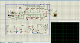
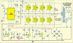
In this power inverter circuit,I am unable to do simulation by using proteus.specially to design transformer,is it any other way same circuit can simulate
Please help me on the transformer side
--- Updated ---
Please help me on the transformer side
Attachments
Last edited: