Continue to Site

Welcome to EDAboard.com

Welcome to our site! EDAboard.com is an international Electronics Discussion Forum focused on EDA software, circuits, schematics, books, theory, papers, asic, pld, 8051, DSP, Network, RF, Analog Design, PCB, Service Manuals... and a whole lot more! To participate you need to register. Registration is free. Click here to register now.

Converting Variable Frequency TTL to fixed amplitude sine wave

Amr Wael

Member level 5
Joined
Jul 13, 2020
Messages
84
Helped
0
Reputation
0
Reaction score
1
Trophy points
8
Activity points
852
Hello,
I have a VCO circuit based on 4046 IC that generates TTL that varies with input voltage.
I would like to convert this variable frequency signal to sine wave with fixed amplitude (Bandwidth less than 1MHz).

I tried using an RC or LC filter however , the amplitude varies with the frequency so it ended up with signal similar to AM instead of FM.

Is there an easier method to convert the VCO output TTL signal to sine with fixed amplitude ?
____________________________________________________________________________________________________________________________
If not is there a method to compensate for the variation in the amplitude or to damp the signals equally to get a fixed amplitude at the end of the day?

Thank you very much in advance.
 
Generating a constant amplitude sinewave from a variable frequency square-wave is not an easy problem.

One way to maintain a (near) constant amplitude sinewave is to use an AGC (Automatic Gain Control) circuit.
That requires a variable gain element to control the amplitude, such as a VGA (Variable Gain Amplifier) or an analog multiplier.
TI and Analog Devices have a number of VGA IC amps that may work for this purpose.

Another, more complex way, would be to use a high-speed micro to generate a sinewave from a lookup table using a D/A converter.
The micro would set the sinewave frequency to be equal to the square-wave input.
 

    FvM

    Points: 2
    Helpful Answer Positive Rating
Hi,

what frequency range?
And how much distortion / overtones do yo allow?
And what amplitude precision do you expect over the frequency range?

Please give numbers with units.

Klaus
 
This method has a shift register outputting to a binary-weighted resistor network.
Smooth the jaggy waveform with a simple capacitor filter. The same capacitor can do a passable job covering a large range (say 1:10). Usual practice is to split up a large frequency coverage into several smaller ranges.

Here the clock rate is 12 times the desired output frequency. You can hook up an identical resistor network to the Q terminals to obtain a second waveform at opposite phase. If you desire finer resolution, add more stages.

You can run a simulation with 8 stages, at
falstad.com/circuit
Click the Circuits menu and look for the Analog/Digital category.
The circuit is named 'digital sine wave'.

quasi sine wave from shift register weighted resistor network (6 D flip-flops).png
 
Last edited:
Just as an aside you can get 5 + decades of range with very stable output
using a DDS chip, and a micro (with A/D to implement V control side and
drive DDS thru I2C). And you get phase control as well.

An example of a one chip SOC version (A/D was not used but trivial to implement,
its also onchip):


Regards, Dana.
 
"Nice design", even with inflation, packing 4 DDS and 4 Wavedacs on a chip, and lots of other stuff
available for use.....

1707261207184.png


Actually dev board started ~ 8 years ago, $ 10, then pre Covid went to $15, and now its $20.

Like the price of food and so much more, and general semiconductor shortage added on top
of inflation, and here we are. Still quite cost effective.....given what you get in one SOC. And
the board has 2 5LP parts on it, break off one after done with one project, and use it as a GP
programmer, or in another application.


Regards, Dana.
 
Last edited:
It’s easy to make a triangle wave and diode soft clipping to 5% THD and better with more effort, if you’re not a digital guy but need good specs. for tolerances and linearity and range.

or consider make vs. buy.
 
Tunable filter, current source with AGC driving a cap, state variable osc.........

Just google "squarewave to triangle converter"


Regards, Dana.
 
Although missing is @danadakk 's SOC approach, TI's summary demonstrates how to choose based on specs for range and distortion and tolerance with tradeoffs.

1707327069334.png


I wonder how BK designed their wide range linear FM VCO's.

recently someone said "BK Precision 3010 function generator for only $35 CDN. Works a charm. 0.1 Hz to 1 MHz, sine, square and triangle waveforms. Adjustable offset and both TTL and variable level outputs."

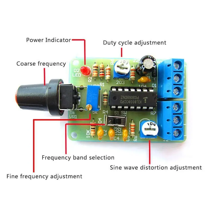
The cheapest solution uses a triangle shaper from a 555 in a kit for < $1 https://www.aliexpress.us/item/3284...6b82f0&afSmartRedirect=y&gatewayAdapt=glo2usa

or the ICL8038 version

 
Last edited:
Another elegant approach :


Regards, Dana.
--- Updated ---

And mo :


And then there is : https://www.arborsci.com/products/mechanical-wave-driver

Use the pulse out of VCO to drive a solenoid that then strikes a wind chime tube,
attached to a MEMS micropho ne, and amplifier........almost forgot a complex acme
screw driven pipe extender to tune the frequency.......


Regards, Dana.
 
Last edited:
Little old school solution:

TTL pulses drive an amp with LC tank and its C is changed by rotating capacive trimpot with stepper motor.
The const. amplitude of LC is held by simple feedback.

Also changing the L is possible by inserting core inside coil by stepper motor.
 
Thank you all , I have decided to use STM32 MCU with an ADC input for Frequency tune and SPI Communication with AD9833 to generate the Sine wave.
This solution is similar to Dana's Solution.
I would like to thank everybody for their solutions
 
"Nice design", even with inflation, packing 4 DDS and 4 Wavedacs on a chip, and lots of other stuff
available for use.....

View attachment 188449

Actually dev board started ~ 8 years ago, $ 10, then pre Covid went to $15, and now its $20.

Like the price of food and so much more, and general semiconductor shortage added on top
of inflation, and here we are. Still quite cost effective.....given what you get in one SOC. And
the board has 2 5LP parts on it, break off one after done with one project, and use it as a GP
programmer, or in another application.


Regards, Dana.
You could also use any inexpensive microcontroller with a built in ADC to generate your sine waves…Well under $20.
 
But can you get 4 DDS and 4 DACs for "Well under $20" and all this on 1 chip ? -

View attachment 188560

Do this on your low end chip : https://www.edaboard.com/threads/test-bed-dds-and-wavedac-burst-tool.393572/,
just one of hundreds of examples of capability.


Regards, Dana.
My low end chip doesn't NEED to do that. Why pay for what you don't need? I know you love the PSOC, but OP asked for a sine wave generator, not an LCD controller or ADC or any of the other stuff. A $0.40 ATTINY or PIC or similar will do what they asked.
 
My low end chip doesn't NEED to do that. Why pay for what you don't need? I know you love the PSOC, but OP asked for a sine wave generator, not an LCD controller or ADC or any of the other stuff. A $0.40 ATTINY or PIC or similar will do what they asked.

Totally agree, if you dont need most of chips resources why pay for that.

But OP did say :

I would like to convert this variable frequency signal to sine wave with fixed amplitude (Bandwidth less than 1MHz).

How are you going to get that out of an ATTINY at 1 Mhz or less with fixed amplitude ? I am thinking
additional HW needed, and we dont know how much distortion, freq accuracy,. resolution, latency,
amplitude accuracy OP is targeting......

@OP, can you comment on all target goals you need in design ?


Regards, Dana.

PS : Barry I do love PSOC, ARM, Freescale IMX, Atmel, Coldfire, 2900 BitSlice, COPS, Scamp, PACE (some of these date me)......
 

LaTeX Commands Quick-Menu:

Part and Inventory Search

Welcome to EDABoard.com

Sponsor

Back
Top