Continue to Site

Welcome to EDAboard.com

Welcome to our site! EDAboard.com is an international Electronics Discussion Forum focused on EDA software, circuits, schematics, books, theory, papers, asic, pld, 8051, DSP, Network, RF, Analog Design, PCB, Service Manuals... and a whole lot more! To participate you need to register. Registration is free. Click here to register now.

analyze and find oscillating frequency

akbarza

Full Member level 2
Joined
Dec 18, 2013
Messages
131
Helped
0
Reputation
0
Reaction score
0
Trophy points
1,296
Activity points
2,556
hi
I found the below schematic in an Lm358 datasheet that belongs to www.onsemi.com.
by attention to the pic, in the datasheet is written that for R3=R1||R2 then the oscillation frequency is f=R1*Rc/(4*c*Rf*R1). but there is no Rc in the schematic.
1)how can analyze the circuit to obtain a formula for frequency?
2)can explain to me why in node triangle_wave, the shape of oscillation is a triangle wave, and also for node square_wave?
3) as we know this circuit will be connected to another circuit and it causes a load effect. How can I import the role of load in the schematic?
4)suppose the design is for a special frequency and R's and c are determined for that frequency. is there any condition on Opamp as Unity gain bandwidth or others that Opamp must satisfy?
thanks
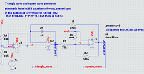
 

Attachments

  • triangle_generator.png
    triangle_generator.png
    49.2 KB · Views: 93
hi
I discussed the matter of impedance calculation in #28
can anyone guide me on how to calculate(or measure) the impedance?
--- Updated ---

Hi,

The thread currently has more than 1k views. Every single member who wants to helo needs to do the search for the datasheet.
Do yourself a favour and post a link to the datasheet directly at the manufacturer site.
1x your effort vs 1000x the helpers effort and the risk to talk about different surces of informations.

Klaus
hi
i read:
https://www.onsemi.com/download/data-sheet/pdf/lm358-d.pdf
 
Last edited:
Most easily, you look at the basic inverting amplifier configuration with two resistors. If you assume ideal OP, no calculation is necessary because you can consider the inverting input as virtual short.
 
Hi,
I discussed the matter of impedance calculation in #28
can anyone guide me on how to calculate(or measure) the impedance?
Impedance of left side of the 1M.

there is this 100k resistor. It domonated the total impedance.
One can be sure that toatl impedance is below 100k.

If you want to die deeper then caclualte the impedance of the connected capacitor:
With the well known formula: Xc = 1 / (2 * Pi * f * c)
since it´s in series with the signal ... the true "source" impedance through the 1n capacitor is a bit higher.

Without complicated calculations I expect all three RCs to generate 180° phase shift. (needed for oscillation) So each single RC about 60°.
For 60° phase shift Xc needs to be about twice of R.
So I expect the Xc of the 1nF to be about 2*100k = 200k.

To calculate the total impedance of 100k (R) and 200k (Xc) you have to use Xt = 1 / (1/R + 1/Xc) = about 66k.

This all is just done without caclulator, just to give a feed about what to expect. Nothing precise.

***

If you want to do it more precisely I recommend to calculate the impedance beginning
* from the OPAMP´s output (considered to be close to 0 Ohms) --> 100n --> 10n --> 1n --> 1M for sure including all Rs.

Klaus
 
Input Z calculation, see attached. Degenerate the stage to simple Inverting amp, NI input grounded.

A sim :

1704202444112.png


Regards, Dana.
 

Attachments

  • DIFFER~2.PDF
    373.5 KB · Views: 51
Last edited:
Not sure what "Impedance @ R1" is in your simulation. Original question:
I want to know the impedance seen from the left of the 1M-ohm resistor, what can I do? must I break the connection of opamp's output and 100n cap? or it is not necessary?
In my understanding this doesn't refer to a node impedance but to load impedance generated by R1 + inverting input impedance (effectively 0 in the frequency range of interest).

Background of the question is, as I think, calculation of phase shift network load.
 
Last edited:
I thought it was 100K ohm in original post.

I have an inconsistency in the simulator and am trying to get answer, stay tuned.


Regards, Dana.
 
Hi,
Not sure what "Impedance @ R1" is in your simulation. Original question:
One question - many possible answers.

In post I thought the OP was asking for the source impedance ... provided to the 1M resistor ..

I´m not sure now whether this is what the OP was asking for.

Klaus
 
I had an error in post #45, in way Z probe in sim was used. Below corrected. But I am suspicious
of sim because internal comp pole seems to occur not at 10 Hz but at .1 Hz, two decades earlier.
So I did a plot w/o integrating cap, 100 G ohm fdbk R, and it does show open loop pole at ~10Hz.

1704226627652.png


Regards, Dana.
 
Last edited:

LaTeX Commands Quick-Menu:

Part and Inventory Search

Welcome to EDABoard.com

Sponsor

Back
Top