Continue to Site

Welcome to EDAboard.com

Welcome to our site! EDAboard.com is an international Electronics Discussion Forum focused on EDA software, circuits, schematics, books, theory, papers, asic, pld, 8051, DSP, Network, RF, Analog Design, PCB, Service Manuals... and a whole lot more! To participate you need to register. Registration is free. Click here to register now.

Oscillating current clamp...how to stop oscillation?

cupoftea

Advanced Member level 5
Joined
Jun 13, 2021
Messages
2,611
Helped
54
Reputation
108
Reaction score
115
Trophy points
63
Activity points
13,685
Hi,
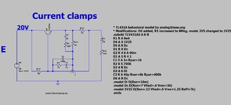
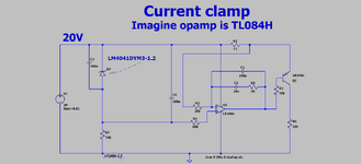
Fig 24, page 11, is a current clamp, using TLV431, but such simplicity may oscillate.


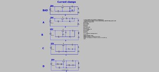
Which of the attached circuits are least likely to oscillate? (LTspice and jpeg)
Note that there is no output capacitance, and here lies the harbinger of the danger of the oscillation

Here is a previous thread on it.

Also attached the TLV431 spice model etc
 

Attachments

  • TLV431 current clamps.jpg
    TLV431 current clamps.jpg
    133.3 KB · Views: 52
  • tlv431as.zip
    1.5 KB · Views: 44
  • TLV431 current clamps.zip
    2.1 KB · Views: 51
Last edited:
None of the circuit variants is providing useful loop gain compensation.

By connecting shunt directly to ref pin you are effectively shorting compensation, there must be a series resistor to increase ref node impedance. Secondly connect the compensation RC series circuit between cathode and ref pin. Set up a loop gain simulation.
 
Thanks, the attached appears to conform to your kind suggestions.
I would like to drop away from the type 3 bits to save component count.
(LTspice and jpeg as attached).

Actually i think C2 and R1 should lie across R14 instead...Would you agree?
 

Attachments

  • TLV431  stabilized.jpg
    TLV431 stabilized.jpg
    203.5 KB · Views: 39
  • TLV431 current clamp_1.zip
    1.1 KB · Views: 53
The compensation scheme isn't bad now and could be used if the circuit has stability problems in a different implementation. With given shunt and load dimensioning it hasn't.

Only the first circuit in post #1 is unstable due to misplaced C3.
--- Updated ---

Actually i think C2 and R1 should lie across R14 instead...Would you agree?
Not at all.
 
Hi,
Regarding the above currrent clamp which uses a TLV431, why instead, would you ever use the attached type of current clamp which uses an opamp?
(i mean, the TLV431 version looks so much cheaper and better that i wonder why anyone would use the opamp version? There is the bias current in
the TLV431 which ends up in the clamped current too, but its just a few mA)
 

Attachments

  • current clamp with opamp_240114.png
    current clamp with opamp_240114.png
    40.9 KB · Views: 36
  • Current clamp with opamp_240114.zip
    1.1 KB · Views: 44

LaTeX Commands Quick-Menu:

Similar threads

Part and Inventory Search

Welcome to EDABoard.com

Sponsor

Back
Top