Salvador12
Full Member level 4
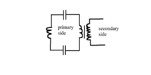
So I have a curious question. I have a loop with two capacitors and two inductors. The first standalone inductor is a high frequency generating coil within this loop, the second inductor is a primary of a transformer. The capacitors are coupling capacitors.
my question is this, if the capacitors have low value then in order for me to be able to transfer any real current i need that current to be at a high frequency where the reactance of the capacitors is low (comparable to circuit resistance) and that is fine for me.
but what will happen once the primary coil with the transformer is introduced to the loop as shown in the attached picture, assuming the primary of the transformer can have the same impedance as the high frequency current generating coil on the left side ?
The idea is to have high frequency PWM current in the loop of the primary side of the transformer and then have low frequency AC on the secondary side of the transformer, where the transformer core and secondary winding with it's high inductance serves as the filter but the primary low inductance side coil together with the capacitors can have high frequency current in the loop. Is this possible or will the transformer even with a low inductance primary still choke the high frequency current in the primary loop given the primary of the transformer is in series with the loop?
Or maybe I need to attach the transformer primary parallel to the main loop creating a parallel LC instead of a series one as shown in the picture.
I appreciate your thoughts.