Continue to Site

Welcome to EDAboard.com

Welcome to our site! EDAboard.com is an international Electronics Discussion Forum focused on EDA software, circuits, schematics, books, theory, papers, asic, pld, 8051, DSP, Network, RF, Analog Design, PCB, Service Manuals... and a whole lot more! To participate you need to register. Registration is free. Click here to register now.

About MOSFET switch problem

Status
Not open for further replies.
Coil power: 0.36W, 0.45W

Based on that the current is about 0.4w/12v=33mA

I think it should be working.
What is the collector voltage when the base is driven with 3v3 (transistor on)?

Thanks. The board is not wif me now. I will measure it later.
But what do u think the collecor voltage should be?
Is there any other value i should troubleshoot?
 

According to your link Coil pick-up voltage: <=75% so for 12v this is 9v

One side of the relay is connected to 12 v so if the collector is up to 2-2.5v the replay should still turn on (12v-2.5v=9.5v)
 
Why r u going back to bipolar transistor ?
use mosfet and put the relay in the drain its is not professional to ask arm to let -out 2.6ma to base it will heat-up and may burnout in the long run.
 

According to your link Coil pick-up voltage: <=75% so for 12v this is 9v

One side of the relay is connected to 12 v so if the collector is up to 2-2.5v the replay should still turn on (12v-2.5v=9.5v)

Sorry guys. I have put the transistor the wrong way. Now it's working with the 1k base resistor already. Thanks for the advice.

---------- Post added at 08:58 ---------- Previous post was at 08:55 ----------

Why r u going back to bipolar transistor ?
use mosfet and put the relay in the drain its is not professional to ask arm to let -out 2.6ma to base it will heat-up and may burnout in the long run.

I'm not using an ARM. I'm using pic18F25k20. It output 3.3V also.
Can this mcu let out 2.6mA to base in the long run a good idea?
 

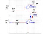
Hi guys, I have another problem. Below is my circuit:
LED.png
The LED is from a 7 segment 5.5 inch LED. I want to use 3.3V and transistor to switch on the LED which is 12V. I want to have a switch on the 12V side and the GND side. Can this circuit work?
 

Q1 is fine as a low side switch but Q4 is connected as an emitter follower, what this means is that the emitter voltage will be equal to the base voltage -0.7v (the Vbe drop) so the led anode will get 2.1v , if that suits you then fine.
You are also missing a resistor to limit the led current.

Alex
It is for a common cathode 7 segment LED. The circuit above is just for one segment of the LED. From mcu, it can only produce 3.3V or 5V. But my led is using 12v. Q4 is for the mcu to turn on a segment. Q1 is to choose which 7 segment led to turn on. I have 4 pcs of 7 segment led here. Do u understand? Can this circuit work?
 

As I said the emitter output of Q4 will be the base voltage minus 0.7v.
If you give 3v3 to the base then you get 2v6 to the emitter, if you give 5v to the base then you get 4v3 to the emitter, the collector voltage can be 12v or 20v or 30v it will not make a difference.

So if your display can work with the voltage you will get to the emitter of Q4 then the circuit will work or else use a PNP driven by a NPN and connect the collector of the PNP to the anode of the display.

Alex
My this circuit does not work. So i need to find out what is the problem.
You mean change the Q4 to a pnp resistor? What is the voltage of the collector of the pnp or anode of the led?
 

The voltage of the collector will be equal to the emitter voltage minus the saturation voltage (Vce drop).
You have to drive the PNP with a NPN like the example with the P-mosfet shown in the first posts of the thread.

Alex
 

The real thing done in real circuit is 2 signals from mcu .
1 to decide which led to select and the other to select which segment to chose.
so if i want to type "4" on led 3 you must select the segments using 1 port to enable the "4" and power the commom of this led just like my drawing
motor and 7 seg cntrl.PNG

https://www.electronics-tutorials.ws/combination/comb_6.html
 

Since I only have npn transistor on hand, is there anyway I can control my 7 segment led using just npn transistor?
I don't have any datasheet for my 7 segment led. I only know that it uses 12V to turn on each of the segment. I also don't know what is it's turn on current. Then how do I determine the value of the current limiting resistor for the led?
 
Last edited:

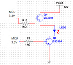
I've change my design to pnp transistor for Q4 on the circuit like below:
PNP_NPN.png
It can work but I thought if we use pnp, aren't that we have to give a low (0V) on the base only it will switch on? But for this design, I have to put high (5V) on the base of pnp to switch it on. Why?
 

It is not a matter of absolute voltage, the PNP turns on when the base is at least 0.7v lower compared to the emitter.
In this case the emitter is connected to 12v so the transistor will be on with 0 or 3v or 5v or 10v in the base so I have no idea why you think that with 0 in the PNP base the transistor is off.

Alex
 
so I have no idea why you think that with 0 in the PNP base the transistor is off.

Alex
From text book. It says that normally PNP is using active low, so 0 is to turn on. For NPN, it's active high, so 1 is to turn on.

---------- Post added at 16:01 ---------- Previous post was at 15:56 ----------

I know! I think if the pnp emitter pin is 5V, then I will have to put 0V on the base only it will turn on right? But my pnp emitter pin is 12V. So, 5V on the base is low enough to turn it on. Am I right?
 

You can easily calculate it with what I wrote in the previous post.

PNP transistor

Ve=5v, Vb=0v, Veb=5-0=5v since this is >0.7v the transistor is on
Ve=5v, Vb=3v, Veb=5-3=3v since this is >0.7v the transistor is on
....
the same for 12v
Ve=12v, Vb=5v, Veb=12-5=7v since this is >0.7v the transistor is on
Ve=12v, Vb=0v, Veb=12-0=12v since this is >0.7v the transistor is on
....

Alex
Then how are we going to off the pnp transistor?
 

Ve=5v, Vb=5v, Veb=5-5=0v since this is <0.7v the transistor is off

Ve=12v, Vb=12v, Veb=12-12=0v since this is <0.7v the transistor is off

This is why you need to use a NPN as a level translator as shown in previous posts
 

Ve=5v, Vb=5v, Veb=5-5=0v since this is <0.7v the transistor is off

Ve=12v, Vb=12v, Veb=12-12=0v since this is <0.7v the transistor is off

This is why you need to use a NPN as a level translator as shown in previous posts

My mcu only can produce 5V. So, I think there's no way I can turn the pnp off using this design.
Actually my 7 segment is something like this:
**broken link removed**
It is power by 12V. I'm using common cathode, so I'm using LD50011A. Each segment of the led anode I have to control using mcu. I have to control the common cathode using the mcu too. So, for each segment, I have to use 2 transistors. That's what the circuit I'm posting on the previous thread.
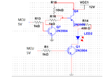
You said that I need a NPN level translator. Is it like below? I added a Q7 NPN transistor.
PNP_NPN_NPN.png
 

you have inverted Q4 and is not correctly connected, the emitter should be connected to the power supply
 

Status
Not open for further replies.

Similar threads

Part and Inventory Search

Welcome to EDABoard.com

Sponsor

Back
Top