Continue to Site

Welcome to EDAboard.com

Welcome to our site! EDAboard.com is an international Electronics Discussion Forum focused on EDA software, circuits, schematics, books, theory, papers, asic, pld, 8051, DSP, Network, RF, Analog Design, PCB, Service Manuals... and a whole lot more! To participate you need to register. Registration is free. Click here to register now.

About MOSFET switch problem

Status
Not open for further replies.
The resistor has a high value and is actually a weak pull up/down resistor , it can't force a value when the mcu drives the gate high or low, it is only there to apply a known state when the mcu output is not enabled or nor connected etc.

Alex
 

Is this reverse when I use bjt transistor? I mean pull up to default on n pull down to default off.
 

This has to do with using a Nmosfet/NPN or Pmosfet/PNP.

A N-mosfet turns on when the gate has a higher voltage compared to the source, the NPN when the base has a higher voltage compared to the emitter.

It is the opposite for the P-mosfet,it turns on when the gate has a lower voltage compared to the source and the PNP when the base has a lower voltage compared to the emitter.

Alex
 
So, can I say that for p mosfet or pnp, pull down resistor for default on and pull up for default off.
For n mosfet or npn, pull down resistor for default off and pull up for default on.
Is it like that?
 

Ok. Thanks Alex!
Just wan to know, how do we normally choose between mosfet transistor switch or bjt transistor switch? I know that mosfet is for high current n power design.
Could u gv some example device that can be turn on by mosfet transistor switch n device that can be turn on by bjt transistor switch?
 

I can't give you specific directions of which one to use, usually both can be used even for low current tasks, a mosfet like 2n7000 can provide a few hundred mA and can be used in place of a small transistor.

In battery circuits a mosfet can give a lower consumption becasue there is no need to feed the gate with current (static operation) unlike a transistor which needs a base current constantly.

So basically it us up to the designer to decide.
 
How do we determine where to put our load? Like ur example, when using p mosfet, the load is put on the drain. But when using n mosfet, the load is put on the source. Is it fixed like that?
 

Normally you connect the load to the drain in both N-mosfet and P-mosfet, you use a N-mosfet with the source connected to the ground and the load to the drain to operate as a low side switch controlling the ground connection to the load and you use a P-mosfet with the source connected to the positive supply with the load in the drain controlling as a high side switch that controls the positive supply connection to the load.

The P-mosfets are more expensive and have worse characteristic (higher ON resistance between drain-source and higher gate capacitance) compared with the N-mosfet and that is why many times we use a N-mosfet as a high side switch.
In this case the drain is connected to the power supply and the load to the source but there is a catch , you have to drive the gate of the mosfet with a voltage higher that the one connected to the drain so for example when you have 12v to the drain you have to apply 12v+bias to turn the mosfet on.

This happens because when the mosfet turns on the source voltage will be almost equal to the drain (for example 10v) so the Vgs which is essentially what turns the mosfet on will be almost 0, if you have applied that same 12v to the gate then you suddenly have no Vgs bias and this creates the problem.


If you drive the gate with the same voltage that you apply to the drain (or lower) then the mosfet will be in a half open state, depending on the gate threshold of the mosfet you will have an increased Vds voltage drop over the mosfet.
nmosfet_high_side.gif

To use it correctly you have to apply to the gate a voltage that is higher then the drain
nmosfet_high_side_correct.gif


Notice the voltage drop on the first circuit which is wrong and in the second which is correct.
The voltage drop depends on the gate threshold , it is lower for IRL2203 that has a gate threshold of 1v and higher for IRF640 which has a gate threshold of about 3-4v

Alex
 

Thanks.

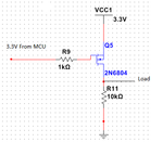
But when I try a P-Mosfet with 3.3V at source like the circuit below, it cannot work. No matter I put 0 or 1 from the mcu the mosfet is still off. Do you know why?
P_MOSFET.png
 

The mosfet will turn off when you apply a voltage that equals (or is close) to the source voltage which is 3v3 in this case and will turn on with 0v at the gate.
If it is not working like that then check the connections and the mosfet pinout of there is something else damaged.
If you try it in a simulator it will will work fine.

Alex
I've tried it already this simulation in multisim. It just won't work.
Any other things to try out to make it work?
 

So you have 3v3 to the source, 3v3 to the gate and the mosfet is still on?
What is the voltage you get at the drain?

Alex

---------- Post added at 11:28 ---------- Previous post was at 11:26 ----------

I sorry, I just noticed that in your previous post you said that it stays always off, not all mosfets are equal , you have to choose a mosfet that can work with a low Vgs of 3v.

You are right. I've changed the P MOSFET from 2N6804 to 2SJ517 and it worked in the simulation. So, what you mean is that we have to choose the mosfet according to the its Vgs value?
Which Vgs to look for in a datasheet? There's Vgs in 'Absolute Maximum Ratings' section. There's also Vgs in 'Electrical Characteristic' section.
 
Last edited:

There is a parameter called Vgs-th which is the min voltage between gate-source that turns the mosfet on , note that this parameter is measured with an output current of just a few uA so you have to use a higher voltage than that.

For 2N6804 this parameter is Min:2v to Max:4v which means that the mosfet can turn on with a min voltage anywhere between 2 to 4v depending on production.
Usually the min you want to use is the voltage shown in curves of the output characteristics graph, 4.5v in this case

Alex
 

New Bitmap Image.GIFHello ahgan
U have a basic mistake u need to know that at all times vgs has to be 3-5v stable .
see post 14 circuit .. now before u switch on u have o volt at pin 2 right ???
now if u manage to switch on u will get 5v at pin 2.... right ????.
(now understand ohm law... or law of voltage ) now u have 5v at pin 2 and 5v from mcu at pin 1 so the fet will stop conducting and maybe u will get partially switching pulses. the same will happen in post 1 circuit. the best solution for u is to add transistor New Bitmap Image.GIF
 

Then if for 2SJ517, from the datasheet the Vgs parameter is between 0.5V to 1.5V. So, does this means I can use something more than 1.5V to turn it on?
 

Then if for 2SJ517, from the datasheet the Vgs parameter is between 0.5V to 1.5V. So, does this means I can use something more than 1.5V to turn it on?

Yes, a voltage of 2v or higher would be fine, the more the output current the more Vgs you should apply in order to achieve a lower Rds-on resistance which will reduce the voltage drop across source and drain.

Alex
 

Status
Not open for further replies.

Similar threads

Part and Inventory Search

Welcome to EDABoard.com

Sponsor

Back
Top