Continue to Site

Welcome to EDAboard.com

Welcome to our site! EDAboard.com is an international Electronics Discussion Forum focused on EDA software, circuits, schematics, books, theory, papers, asic, pld, 8051, DSP, Network, RF, Analog Design, PCB, Service Manuals... and a whole lot more! To participate you need to register. Registration is free. Click here to register now.

About MOSFET switch problem

Status
Not open for further replies.
"min voltage between gate-source that turns the mosfet on "
i read alex post we are talking about the same thing
am i right alex ? he does not understand that once he manages to switch on he cant hold on to this level
 

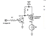
View attachment 73097Hello ahgan
U have a basic mistake u need to know that at all times vgs has to be 3-5v stable .
see post 14 circuit .. now before u switch on u have o volt at pin 2 right ???
now if u manage to switch on u will get 5v at pin 2.... right ????.
(now understand ohm law... or law of voltage ) now u have 5v at pin 2 and 5v from mcu at pin 1 so the fet will stop conducting and maybe u will get partially switching pulses. the same will happen in post 1 circuit. the best solution for u is to add transistor View attachment 73097

Do you have another solution which do not need to add another transistor? My PCB is out of space.
 

wrong question u did not read or understand what i posted
u will need to try better cause people will give up and stop helping

https://www.electronics-tutorials.ws/

There are no wrong question so please don't discourage members from asking questions.

---------- Post added at 12:11 ---------- Previous post was at 12:09 ----------

"min voltage between gate-source that turns the mosfet on "
i read alex post we are talking about the same thing
am i right alex ? he does not understand that once he manages to switch on he cant hold on to this level

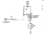
Are we talking about the circuit is post #30 using 2SJ517?
If so I don't see the problem, as long as he drives the gate with 0 the mosfet will be on.

Alex
 
So as overall, N-MOSFET is reverse if compare to P-MOSFET right? I mean in terms of turning off and on signal from mcu. For, N-MOSFET, 0 from mcu is turn off and 1 from mcu is turn on. But for P-MOSFET, 0 from mcu is turn on and 1 from mcu is turn off. Am I right?
 

Please start using quotes because I'm getting confused who is replying to what.

@dselec
I don't understand why do you find it a problem to have the mcu drive the P-mosfet permanently and you are trying to use a latch circuit?

So as overall, N-MOSFET is reverse if compare to P-MOSFET right? I mean in terms of turning off and on signal from mcu. For, N-MOSFET, 0 from mcu is turn off and 1 from mcu is turn on. But for P-MOSFET, 0 from mcu is turn on and 1 from mcu is turn off. Am I right?

Yes and no , it's all about the applied Vgs (gate voltage referred to the source and not the ground), with a Pmosfet that has the source connected to the 12v you can't turn it off with 0 or 5v , it only turns off when the Vgs is 0 so the gate must be 12v too.

Refer to posts #23 and #29
 
Please start using quotes because I'm getting confused who is replying to what.

@dselec
I don't understand why do you find it a problem to have the mcu drive the P-mosfet permanently and you are trying to use a latch circuit?


Yes and no , it's all about the applied Vgs (gate voltage referred to the source and not the ground), with a Pmosfet that has the source connected to the 12v you can't turn it off with 0 or 5v , it only turns off when the Vgs is 0 so the gate must be 12v too.

Refer to posts #23 and #29

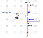
Like the circuit that I showed just now:
P_MOSFET.png
The P-MOSFET only turn ON when I put 0 (0V) on the gate and turn OFF when I put 1 (3.3V) on the gate.
Just asking out of curiosity. What do I have to do to the circuit if I want 0 on the gate to turn OFF and 1 on the gate to turn ON the P-MOSFET?
 

One solution is to use a transistor in a common emitter configuration which will operate as an inverter driving the P-mosfet, like shown in post #4.

Another solution is to use a low side switch using a N-mosfet.


Alex
 
One solution is to use a transistor in a common emitter configuration which will operate as an inverter driving the P-mosfet, like shown in post #4.

Another solution is to use a low side switch using a N-mosfet.


Alex
I see.
Thanks for all the answers Alex! Really appreciate your time!
 

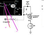
I don't see how the diode circuit could work, the cathode voltage is 24v and the anode 0 or 5v so the diode is always reverse polarized.

Alex
 

hi friend,

i will try to solve to your problem.

i think ur using arm processor. each pin configured as pullup,pulldown,open drain. otherwise any open drain pin is available, connect that pin to directly gate of maosfet and resistor(10k) connect source to gate. then i think ur problem will solve.
 

Even for open drain pins there is a limit to the allowed voltage, I don't think you can connect 24v to an open drain pin of any mcu.

Alex
 

Last edited:

Even if the mosfet source is connected to 5v the diode will still not conduct, it will have 5v in the cathode so 0 or 5v in the anode will not make a difference, he will never be able to apply 0v to the gate this way so the mosfet will be always off.

Alex
 

Right so now there is a problem .
the supply can be 12v 24v 48v or 480vdc and i know from experience that there must be some kind of protection.
maybe he should use an opto, i cant understand why he is changing the voltage all the time .
we can Emmit the diode-for 5v supply and the next-thing we know he will change the supply for some reason and his arm will go to heaven.!!!
maybe we can add a T network of resistor 5v zeren and resistor
 

Hi there,
For the circuit on thread #11 in this topic, i use a npn transistor as a switch to turn on device connected to the collector. Now, instead of R6 resistor on the collector, i change it to a 12v relay. So, now i want to use the npn transistor to turn on the 12v relay. The voltage from mcu which connected to the base is still 3.3v for high and 0v for low. So, what is the suitable value for R2 which is the base resistor so that it can turn on the transistor? I used 1k resistor but it won't work.
 

1K would provide to the base (3.3v-0.7v)/1K=2.6mA

As I said the current of the base should be about 1/10 to 1/20 of the output current so how much current does your relay need?
After calculating the needed current you have to make sure that the mcu can provided it too (within specs)

Alex
 

1K would provide to the base (3.3v-0.7v)/1K=2.6mA

As I said the current of the base should be about 1/10 to 1/20 of the output current so how much current does your relay need?
After calculating the needed current you have to make sure that the mcu can provided it too (within specs)

Alex

My 12v relay is as below:
**broken link removed**
I do not know how much current the relay need cos i could not find the datasheet. Do you know how much current it need? What is a normal current value from ur experience?
 

Coil power: 0.36W, 0.45W

Based on that the current is about 0.4w/12v=33mA

I think it should be working.
What is the collector voltage when the base is driven with 3v3 (transistor on)?
 

Status
Not open for further replies.

Similar threads

Part and Inventory Search

Welcome to EDABoard.com

Sponsor

Back
Top