Continue to Site

Welcome to EDAboard.com

Welcome to our site! EDAboard.com is an international Electronics Discussion Forum focused on EDA software, circuits, schematics, books, theory, papers, asic, pld, 8051, DSP, Network, RF, Analog Design, PCB, Service Manuals... and a whole lot more! To participate you need to register. Registration is free. Click here to register now.

About MOSFET switch problem

Status
Not open for further replies.
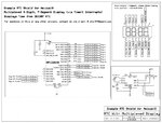
you have inverted Q4 and is not correctly connected, the emitter should be connected to the power supply

Sorry. I've connect the Q4 correct again. What do I put on base Q7 to turn the led off? I've tried it, no matter I put high (5V) or low (0V) on the base of Q7, it still turn on. How do I off it?
 

0v at the base of Q7 turn it off so there is no current through R15 which means no voltage drop so the base of Q4 gets 12v and turns off
 

"I'm using pic18F25k20. It output 3.3V also.
Can this mcu let out 2.6mA to base in the long run a good idea?"u can use darlingtion transistiors to reduce current to microamps... checkout how much the pic can sink current and i will give u another idea.
 

0v at the base of Q7 turn it off so there is no current through R15 which means no voltage drop so the base of Q4 gets 12v and turns off

Do I put one pnp Q7 transistor on each of the 7 segments? Or I put just one pnp Q7 transistor which can drive all 7 segments?
 

The usual way is to drive the seven segment in parallel and control through the common anode or common cathode pin which display to turn on.
 

The usual way is to drive the seven segment in parallel and control through the common anode or common cathode pin which display to turn on.

I know we drive the 7 segment in parallel.
There are 7 segment, so does this means we have 7 pnp transistors? Each pnp transistor connect to each segment.
 

Yes, one transistor to each segment to be able to turn it on/off independently

Alex
 

Yes, one transistor to each segment to be able to turn it on/off independently

Alex
Not quite accurate 1 transistor for each 7 seg and one transitor for each segment but all same segments joined together no transistor for them
**broken link removed**
 

Not quite accurate 1 transistor for each 7 seg and one transitor for each segment but all same segments joined together no transistor for them
**broken link removed**

I already said in post #85 that all segments are in parallel
The usual way is to drive the seven segment in parallel and control through the common anode or common cathode pin which display to turn on.

And the OP said that he already knows that
I know we drive the 7 segment in parallel.

So I don't see any inaccuracy in what I said.
 

My design work already.
Just want to know, like for my design, the PNP transistor will have to connect with a NPN transistor only it can turn off. Then what is the purpose of using a single PNP transistor in designs since it can't be off?
 

I don't know which design you refer to but if you were using 5v for your display (5v in the PNP emitter) and you had a 5v microcontroler then you wouldn't need the npn.
 

Schematic - RTC w&#105.jpgRight ALEX u did 90 posts will give me/u/ anybody a migraine so now we dont know what design he is talking about and why he still is asking help with pnp/npn transistors ...any way i gave him the whole circuit so whats holding him back ?

---------- Post added at 13:59 ---------- Previous post was at 13:57 ----------

**broken link removed**
 

Attachments

  • Schematic - RTC w&#105.jpg
    Schematic - RTC w&#105.jpg
    90.7 KB · Views: 63
Thanks for everybody's help :)

---------- Post added at 12:26 ---------- Previous post was at 10:48 ----------

Just for a thought. Is there any driver ic which can input 5V but output 12V? Then I may no need use all those transistor.
Something like 74LVX3245 where it change the signal from 3.3V to 5V.
 

You can use a high side switch array like UDN2982
 

You can use a high side switch array like UDN2982

Noted. Thanks.
For the 7-segment led like the one in this website:
**broken link removed**
One segment contained 14 led. Then how do we calculate the value of the current limit resistor? Because normally we put one resistor for one led. Now we got 14 led just for one segment.
 

The equation to calculate the resistor is

R = (Vinput-Vled) / Iled

I don't see a forward voltage drop spec in the link, not even the 12v that you specify as the operating voltage

Having multiple leds is not a problem if you know the Vf of the led , for example you may have one 2v led and used Vled=2v in the equation or have 3 leds in series and use Vled=6v , this is not a problem.

Alex
 

CountDown41.png
I've found this design on the net. Their 7 segment LED is using 12V too. But they are using TPIC6C595 alone to drive without using any transistor. Can it work?
 

You mean one IC for each character? Then if I got 4 character, then I have to use four TPIC6C595?
Is it for this design, we have to use common anode 7 segment display?
 

Yes for four display you need four IC.
The IC are just power shift registers and the schematic shows that they are connected in chain
SER0 -> to IC of next digit
You can use common anode display
 

Status
Not open for further replies.

Similar threads

Part and Inventory Search

Welcome to EDABoard.com

Sponsor

Back
Top