Continue to Site

Welcome to EDAboard.com

Welcome to our site! EDAboard.com is an international Electronics Discussion Forum focused on EDA software, circuits, schematics, books, theory, papers, asic, pld, 8051, DSP, Network, RF, Analog Design, PCB, Service Manuals... and a whole lot more! To participate you need to register. Registration is free. Click here to register now.

What would be the oscillation frequency?

Status
Not open for further replies.

aryajur

Advanced Member level 3
Joined
Oct 23, 2004
Messages
793
Helped
124
Reputation
248
Reaction score
37
Trophy points
1,308
Location
San Jose, USA
Activity points
7,788
Hello,
Attached is the frequency response of an ideal opamp (Except it has finite gain = 1e7) Poles are real at frequencies: 159Hz, 100Khz, 100MHz. So now the question is if we put this opamp in a unity gain feedback configuration (Opamp Buffer) and give a step input to the + terminal, what would be the frequency of the oscillating output?
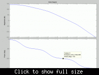
 

the point at which the phase is 180° is the point the feedback changes to positive and leads to oscillations.... the graph is not clear.... just note the freq corresponding to 180° phase shift....
 

Thats what I figured but when I actually simulate it the period of oscillation is 80n which is 12.5MHz while the 180 deg freq is around 2-3MHz
 

actually i'm a little confused... actually the gain and phase are usually given with respect to input and you are talking about output frequency....
 

Thats true that gain and phase are with respect to input signal but as you can see the system is unstable. So as I mention in my first post that when I give a step input the output would start ringing and since the phase margin is negative the ringing would increase in amplitude. So the main question is what would be the frequency of ringing?
Intuitively it does seem that it should be the 180 deg phase shift freq. But when you actually simulate it or if you solve it analytically both give the same frequency of ringing and that turns out to be the a different frequency. So this is the thing that is confusing me and it is turning up many more confusions.
 

The above open loop frequency response shows an unstable system, if I put it in unity gain feedback (β=1) and give a step input what is the oscillation frequency?
 

"simulate it the period of oscillation is 80n which is 12.5MHz while the 180 deg freq is around 2-3MHz"

on your bode plot, i assume it may not be obvious to distinguish between 12.5Mhz and 2-3 MHZ by your cursor, i would suggest you to manually increase
the ac simulation steps ( try steps between 1000 to 10000), then you may have much better resolution and probably you will see the 180 phase shift is just
12.5Mhz, try it and let me know, i 'd like to see the result.
 

Hello maninnet, the bode plot clearly shows that 180deg phase shift has already shifted before the 1e7(i.e. 10MHz) frequency. The bode plot is correct, I have verified in 2 simulation software. If you would like to investigate the 180deg phase shift frequency for the system just solve for it. The poles as I mentioned earlier are:

p1 = 159.155Hz
p2 = 100KHz
p3 = 100MHz

DC Gain is A=1e7

You can go further and solve the system's step response and find the output and calculate the frequency theoretically and see that it won't match with the 180 deg frequency.
 

Closed Loop unity gain Bandwidth ~17.62 Mhz. All this information can be derived since i have gived all the information about the open loop system i.e. the 3 poles and te DC gain.
 

Here is the derivation ,I divided it in I parts so that you don't needs points to download.
 

Attention: the operation points for open-loop response and closed-loop response are different.
That's to say, oscillation will change the operation point, so does the frequency response. pay attention to the large signal response, just like the ring oscillator.
 

i do not have matlab installed ,
could you use the following code to plot your close loop system:

tao1=1/(2*pi*159.15);
tao2=1/(2*pi*100e+3);
tao3=1/(2*pi*100e+6);
A=1e+7;
tf1=tf([1],[tao1 1]);
tf2=tf([1],[tao2 1]);
tf3=tf([1],[tao3 1]);
H=A*tf1*tf2*tf3;
Hunity=H/(1+H);
bode(Hunity)
 

The closed loop response is given low confirming the oscillation frequency is around 12.5MHz. Also there is no quesion about different large signal oscillation frequency and small signal oscillation frequency, the circuit is purely linear, there are no non linearities.
 

1. could you also post your step response?

2. how do you build you this ideal opamp?

2. in the close loop plot, but the phase does not reach 180 degree at overshoot, how to intepret?
 

Attached is the step respose for the circuit. The time period is 80ns. To create an ideal opamp use the VCVS elements together with R and C components to create the poles at the desired frequencies. In the closed loop response the phase lag due to the 3rd pole kicks in and therefore does not allow the phase to reach 180 deg due to the complex pole pair.
 

Why i want to ask the frequency of closed loop bandwidth is because I would consider we should look at closed loop bandwidth to relate to the oscillation frequency, as when you make it UGB, it is a closed loop instead of an open loop, so open loop analysis may not be wrong!
 

aryajur:

I plot the open loop of your opamp as shown in the picture, i don't understand why the phase in your open loop plot is different from mine (after the 2nd pole), even though they are equivalent. And could you post your schematic of your ideal opamp, i just know how to implement your open loop transfer function with several vccs and RC (like a filter) but don't know how to do it with only one vccs and and several RC.
 

Status
Not open for further replies.

Part and Inventory Search

Welcome to EDABoard.com

Sponsor

Back
Top