Continue to Site

Welcome to EDAboard.com

Welcome to our site! EDAboard.com is an international Electronics Discussion Forum focused on EDA software, circuits, schematics, books, theory, papers, asic, pld, 8051, DSP, Network, RF, Analog Design, PCB, Service Manuals... and a whole lot more! To participate you need to register. Registration is free. Click here to register now.

What type of circuit should I use for this (driving 24v with 3.3v)

Status
Not open for further replies.

blapcb

Full Member level 3
Joined
Jan 7, 2007
Messages
188
Helped
2
Reputation
4
Reaction score
0
Trophy points
1,296
Location
Planet earth (most of the time)
Activity points
2,766
I am doing a small box that will simulate some signals which are normally 24v (or 12v). Presently everything is working (i.e. firmware running) and the output is 3.3v TTL (from the micro). But, in order to interface to the equipment being tested, the 3.3v needs to be 24v (or what ever the supply voltage is). What is the best circuit to use for this? I don't want to place a big load on the I/O of the micro. I tried using comperators, it works, but I have a feeling it is not the best solution.
 

Firstly thanks for referring to a great page.
I have used transistors before to rive LEDs etc.
So sorry if this is a totally newbie question, but, in all these circuits (it seems to me) the load is driven by basically connecting the ground (i.e. giving it a path to ground). In this case what I want to do, is just provide a 24v signal when the I/O is 3.3v (and zero when I/O is low). I sort of understand that the device to which I am connecting the output is a "load", but not sure how to wire things up. If I take the output from the collector of the transistor, the circuit will be an inverting one.
 

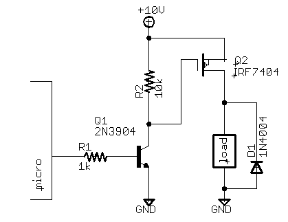
See this for example:
int-switch-p-fet.png
 

What I had been doing was using a comperator like 393 and connecting the micro output to the (-) and a reference voltage of 2.5v to the (+). The output of the 393 will then be zero when the micro is low an 24v (if that is the supply to the 393) when the micro is high.
 

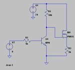
Yes, but in this case you don’t have possibility to supply enough current to the load. Use instead this combination of NPN bipolar and PMOS transistors.
 

Yes, but in this case you don’t have possibility to supply enough current to the load. Use instead this combination of NPN bipolar and PMOS transistors.

Yes I think current is/was one of the issues (causing voltage to drop).
In your proposed circuit, I would just wire to the emitter of the MOSFET? And why do I need the diode if the "load" is not inductive?
 

That’s a general example including some diode protection, you may remove it from your design.
 

How come? :cool:
 

Attachments

  • PMOS sw.GIF
    PMOS sw.GIF
    25.1 KB · Views: 108

Ah...... ! :)

OK now, question is, if I have 8 such channels, can I get a nice SOIC for the PMOS? :)
Seems like a waste of space doing this circuit X 8 out of discreet parts.....
 

Status
Not open for further replies.

Similar threads

Part and Inventory Search

Welcome to EDABoard.com

Sponsor

Back
Top