blapcb
Full Member level 3
- Joined
- Jan 7, 2007
- Messages
- 188
- Helped
- 2
- Reputation
- 4
- Reaction score
- 0
- Trophy points
- 1,296
- Location
- Planet earth (most of the time)
- Activity points
- 2,766
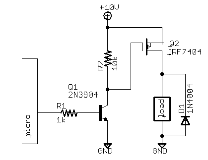
I am doing a small box that will simulate some signals which are normally 24v (or 12v). Presently everything is working (i.e. firmware running) and the output is 3.3v TTL (from the micro). But, in order to interface to the equipment being tested, the 3.3v needs to be 24v (or what ever the supply voltage is). What is the best circuit to use for this? I don't want to place a big load on the I/O of the micro. I tried using comperators, it works, but I have a feeling it is not the best solution.