mohazaga
Full Member level 2
cmos inverter overshoot
Hi ,,,
I design a CMOS inverter using 0.35u process, and I test its output by input different frequency square pulses.
The output of the inverter get distorted after 1M, is that due to RC parasitic introduced by fab. process.
Also, why there is overshoot and undershoot ate beginning of rise/fall of output pulse? is that due of RCL parasitic of IC pad contact?
Could you help please?
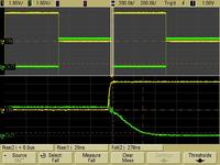
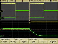
See the output at input of 5k, 50k, 200k, 2M & 5M.
Freq-5KHz
Freq-50KHz
Freq-200KHz
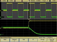
Freq-2MHz
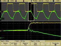
Freq-5MHz
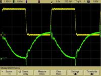
Hi ,,,
I design a CMOS inverter using 0.35u process, and I test its output by input different frequency square pulses.
The output of the inverter get distorted after 1M, is that due to RC parasitic introduced by fab. process.
Also, why there is overshoot and undershoot ate beginning of rise/fall of output pulse? is that due of RCL parasitic of IC pad contact?
Could you help please?
See the output at input of 5k, 50k, 200k, 2M & 5M.
Freq-5KHz
Freq-50KHz
Freq-200KHz
Freq-2MHz
Freq-5MHz