DeepOne
Advanced Member level 2
- Joined
- Feb 26, 2011
- Messages
- 632
- Helped
- 99
- Reputation
- 200
- Reaction score
- 100
- Trophy points
- 28
- Location
- 45N39E, Russia
- Activity points
- 0
Follow along with the video below to see how to install our site as a web app on your home screen.
Note: This feature may not be available in some browsers.
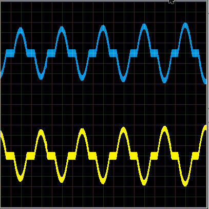
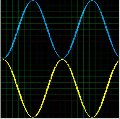
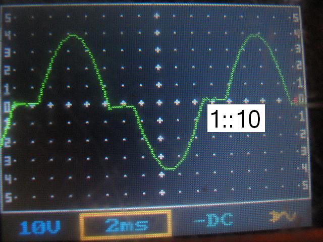
no, wave shape with no load is close to sine.Is the wave shape at no load square?
") and plz upload final version of mega8 both315->220v or transformer 50hz and also tiny13 code
and plz upload final version of mega8 both315->220v or transformer 50hz and also tiny13 codeHe means 315t0 220v version with atmega8(DIP)Hi Deep one, hav a nice day u done awesome job. it's great help
i hav a Q as in previous projects atmel mega8 has generate 4 pwms i.e 2 sine and 2 for square can we use ir2110/2304 high side with 50hz square pwm and low side with sine pwm 37khz ?No need to do push-pull after 315v (350v) push-pull must use a transformer which is useless.