Continue to Site

Welcome to EDAboard.com

Welcome to our site! EDAboard.com is an international Electronics Discussion Forum focused on EDA software, circuits, schematics, books, theory, papers, asic, pld, 8051, DSP, Network, RF, Analog Design, PCB, Service Manuals... and a whole lot more! To participate you need to register. Registration is free. Click here to register now.

Sinewave inverter prototype...

Status
Not open for further replies.
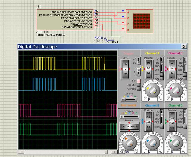
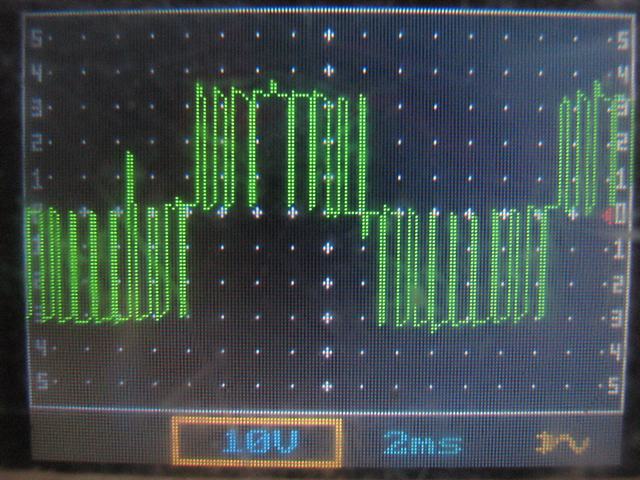
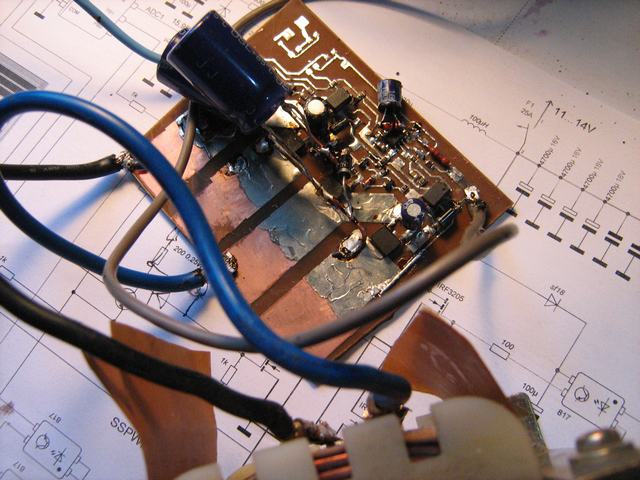
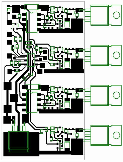
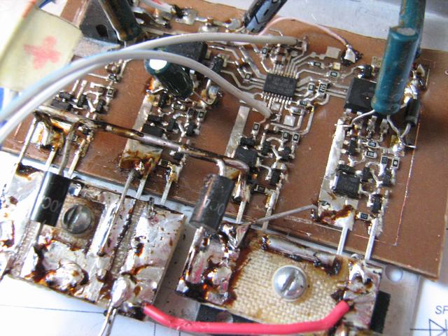
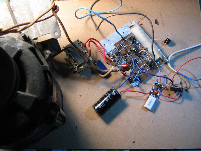
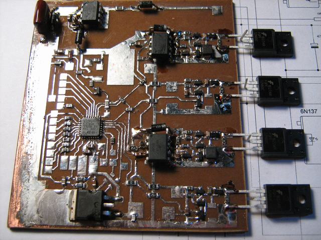
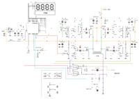
next version of STM8 circuit, looks like it may work.
 
Last edited:

Sorry, Naseerak - that is not work.
BTW, next stm8 prototype - low frequency DC_DC spwm converter.
 

tiny13 software spwm version
 

Attachments

  • t13soft spwm_c&hex&pcb.zip
    78.7 KB · Views: 358
Last edited:

This is old version you posted already
 

No, it is new version, may be similar to old, in something

15 min 25W motor load test is ok.
 
Last edited:

and wave form during load still sine or close to sine?
 

wave form during load still sine or close to sine?
There whole nine pulses on half-wave, so waveform not very close to sine, but this is acceptable for motor application.
Capacitive load is possible to connect to transformer only through inductor.
 

hi DeepOne ,

is there any project whose waveform is puresine wave during motor load ?
 

@Deepone No Sine table perhaps you are calculating the values on the fly..
 

@Waqasjamil
is there any project whose waveform is puresine wave during motor load ?
I do not see such projects, but can be something in someplace with automatic waveform corrections.
However for feeding AC induction motor quite often specially contribute some distortions, for example - like described in
UM0712 ("STM8S three phase control software library")

@Naseerak
As mr.ALERTLINKS already say - in that project used beforehand prepared spwm table. Practically, there is sense to calculate tables on the fly on mcu like STM32.
 
Last edited:

Hi DeepOne,
Can you explain in some detail the functioning of your output current sensing circuit? What is the function of the two interconnected optocouplers (PC817) and what does the 5.1k ohm resistor at the micro's side do?

Also what would the expected output power be when using a single IRF3205 in each side of the H-bridge?

Thanks.
 
Last edited:

Hi, Sghr220.
When output current exceed some value, voltage on current sense resistor go to sufficient value for opening optocoupler and mcu pin to be shorten to common wire. As result mcu switch off power fets (or that is there provided in microprogram).
Optional resistor on mcu side used for increasing hindrance stability, because internal mcu pull-up has too big resistance.
would the expected output power be when using a single IRF3205 in each side of the H-bridge?
i think not more than 500W with 12V feeding
 
Last edited:

Hi, Sghr220.
When output current exceed some value, voltage on current sense resistor go to sufficient value for opening optocoupler and mcu pin to be shorten to common wire. As result mcu switch off power fets (or that is there provided in microprogram).
Optional resistor on mcu side used for increasing hindrance stability, because internal mcu pull-up has too big resistance.

i think not more than 500W with 12V feeding

Thank you DeepOne for the detailed answer.
 

@Deepone what is the carrier frequency and can we adjust the the value of the trigger voltage to adjust the trigger voltage for ADc of the micro. my other question is the use of this circuit for 24v operation.
 

If you bear in mind the last circuit - the carrier frequency is 1kHz with 25 points of pwm resolution. I think it is possible to enlarge frequency up to 5kHz.
adjust the trigger voltage for ADc of the micro
It may be changed in source code or with ADC resistors divider.
use of this circuit for 24v operation
In this case It is necessary to take care of voltage limiting for fets G-S. And adjust voltage for mcu battery voltage detector. Also will be necessary worried about mcu source resistor and, of course about transformer.

Apropos, next prototype

_______________________________________________________________________
modified schematics for project from message #193
 
Last edited:

At the first sight that circuit is work. To say the least 40 minutes 20W motor load test is ok (only spwm generation test process programmed)
 

Attachments

  • c&hex spwm only.zip
    10.1 KB · Views: 251
Last edited:

Last version of that HV spwm modulator with STM8f103f2p6 mcu.
100W motor load test ok, multiple switch off/on mcu&drivers source with +330V on bridge test ok.
 

Attachments

  • c&hex&pcb.zip
    20 KB · Views: 252
Last edited:

Status
Not open for further replies.

Part and Inventory Search

Welcome to EDABoard.com

Sponsor

Back
Top