Continue to Site

Welcome to EDAboard.com

Welcome to our site! EDAboard.com is an international Electronics Discussion Forum focused on EDA software, circuits, schematics, books, theory, papers, asic, pld, 8051, DSP, Network, RF, Analog Design, PCB, Service Manuals... and a whole lot more! To participate you need to register. Registration is free. Click here to register now.

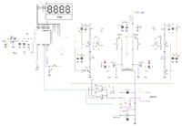
Sinewave inverter prototype...

Status
Not open for further replies.
can we use ir2110/2304 high side with 50hz square pwm and low side with sine pwm 37khz ?
yes, but result of this method is not be good.
 

yes, but result of this method is not be good.
hi DeepOne
thanks for info. as you mention 1,1.2us deadtime require for +315v-220v... would be ir2110 deadtime adjust as require by changing in hardware ?(like bootstrap cap etc ). As many hv ciruit base on ir2110
 
Last edited:

In the most simple event you may reed this in fets datasheet, in source-drain diode reverse recovery time section. For example - reverse recovery time of 2SK3299 - 1,9uS, IRF740 - 0,37us.
would be ir2110 deadtime adjust
is not provided in this microcircuit.
 
Last edited:

You may use IR2153 which is basically a PWM chip but can be used in BRIDGE mode with adjustable dead time.
 

what's voltage across pb1 , pb2 in mega8 pwm ? i got 0.15mv don't no why ?
 

average value around 3V, but this depends on measuring instrument - better if used oscilloscope.
check supply voltage and voltage level on input pins (PD7,PC0,PC1,PC2,PB5)
 
Last edited:

average value around 3V, but this depends on measuring instrument - better if used oscilloscope.
check supply voltage and voltage level on input pins (PD7,PC0,PC1,PC2,PB5)

i used digital oscilloscope but no good result no enough voltage to operate h-bridge drive

- - - Updated - - -

in proteus wave disapear after few sec.

tretertet.PNG
 

wave disapear after few sec
connect PD7 and PC0 to Vss, ADC7 and PC2 to +5V for testing purpose.
__________________________________________________________________________
STM8S test version. Only with spwm, nothing more. 25W load test is ok.
 

Attachments

  • fb_STM8S.zip
    8.2 KB · Views: 186
  • pcb.zip
    76 KB · Views: 213
Last edited:

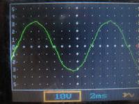
did you check wave form on motor load ?
 

what's about mega8 circuit hv waveform ?
if this mega8 scheme from last schemes waveform must be not bad.
________________________________________________________
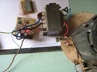
Full version of stm8 firmware, but without deep testing and smoothing corners. However this spwm converter pass 30 min testing with around 100W motor load.
 

Attachments

  • stm8s c&hex&pcb&schm.zip
    90.8 KB · Views: 248
Last edited:

hi DeepOne ,
i appreciate your work. i hav Q would be use same scheme for atmel mega8 instead of stm8s?
 

Hi Waqasjamil. AtMega8 has no hardware pwm dead-time generation, so some scheme would not be used.
 

ok and would be Atmega8 transformer version use for +315v?
 

I did not try so not entrust for this. Can be if contribute some improvements.. but this will much more simply with stm mcu.
 

Dear DeepOne,
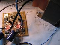
As stm mcu hardly available here ,so i have no option rather than atmel or pic and early i use your scheme mega8 dip version and it's awesome... i successfully run circuit on real hardware . now i try for +315v using ir2110 using same firmware
 

Status
Not open for further replies.

Part and Inventory Search

Welcome to EDABoard.com

Sponsor

Back
Top