DeepOne
Advanced Member level 2
- Joined
- Feb 26, 2011
- Messages
- 632
- Helped
- 99
- Reputation
- 200
- Reaction score
- 100
- Trophy points
- 28
- Location
- 45N39E, Russia
- Activity points
- 0
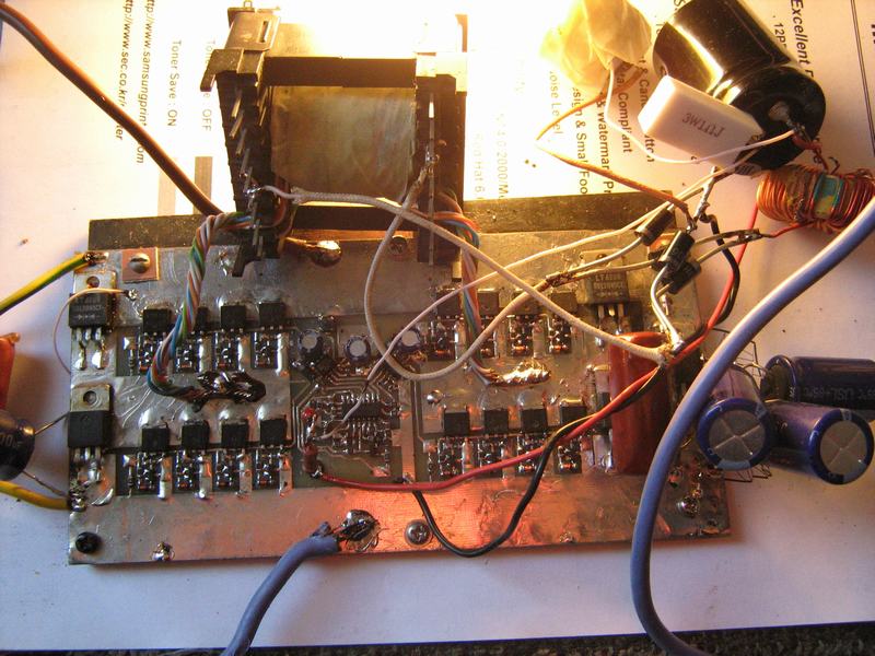
Re: Sinewave inverter prototype.
two opto-coupler is simple switch on/off charger, it is possible not to use it, use one of them or take any external charger.
DIP28 version of AtMega8 is not equal to TQFP32 because it has no adc channels 6&7.
two opto-coupler is simple switch on/off charger, it is possible not to use it, use one of them or take any external charger.
DIP28 version of AtMega8 is not equal to TQFP32 because it has no adc channels 6&7.