Continue to Site

Welcome to EDAboard.com

Welcome to our site! EDAboard.com is an international Electronics Discussion Forum focused on EDA software, circuits, schematics, books, theory, papers, asic, pld, 8051, DSP, Network, RF, Analog Design, PCB, Service Manuals... and a whole lot more! To participate you need to register. Registration is free. Click here to register now.

Sinewave inverter prototype...

Status
Not open for further replies.
Re: Sinewave inverter prototype.

How much power it can deliver in terms of watts.
 
Re: Sinewave inverter prototype.

I do not know. But think is possible to take as minimum 200W from this
 

Re: Sinewave inverter prototype.

Dear!
Is this the limitation of the inverter (350v DC)
PHP:
or H-bridge sine converter?
 

Re: Sinewave inverter prototype.

I bear in mind last scheme. Scheme with 50Hz big iron transformer is limited basically by power of the transformer.
________________________________________
For 350DC>>220AC there was possible use such scheme, with extended to 1us delay. But it not tested on real hardware.
 
Last edited:

Re: Sinewave inverter prototype.

next version, based on cheap Tiny43 mcu.
 

Attachments

  • t43sw_c_hex_pcb.zip
    23.7 KB · Views: 275
Last edited:

Re: Sinewave inverter prototype.

Hi
It is very strange that Tiny43 is expensive than ATmega8 here in Pakistan, This version with big 50HZ Transformer can be enhanced with implementing a charger using the same transformer by using a triac and zero cross detector.
BTW what turns ratio are you using mean 8/280 8/315 or 12/220.
regards
 

Re: Sinewave inverter prototype.

May be it is really strange but that there is as is ). For example, pricelist of most popular local seller - **broken link removed** (1USD=35RUB).
can be enhanced with implementing a charger using the same transformer
Yes, certainly. Because built-in FET diodes is already ready rectifier, and for implementing a charger is remains to switch off bridge and add triac for regulation, at first sight. But may be later. Next winter )
what turns ratio are you using mean 8/280 8/315 or 12/220.
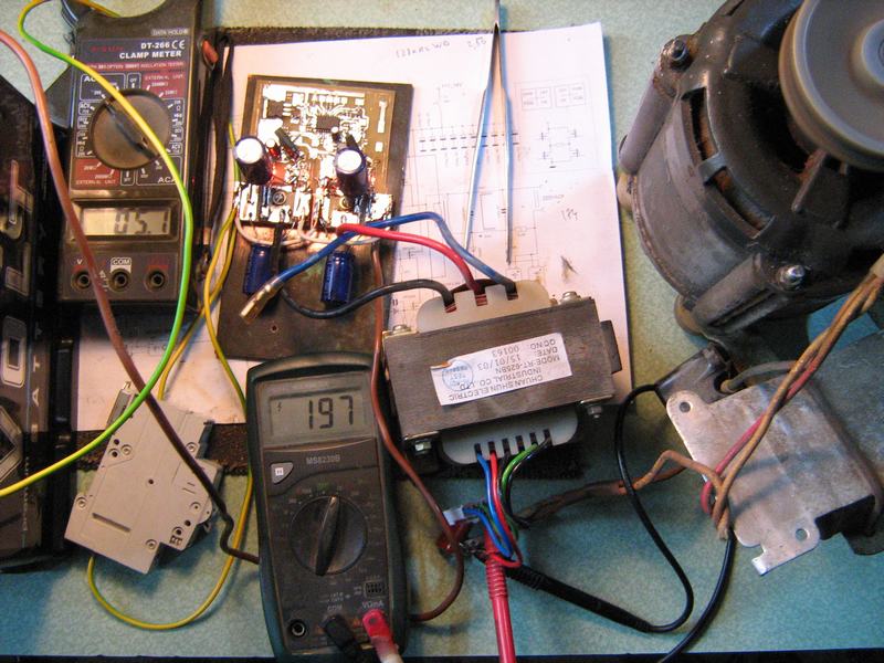
I take transformer from UPS with quasi sine wave output with 1/30 turns ratio, as i see on oscilloscope.
 
Last edited:

Re: Sinewave inverter prototype.

OK
What is the difference between this version (tin48) and the version with Atmega8 shown by you in the earlier posts, as I want to make it with Atmega8 with seven segment display as shown by you early. my question here whether this version is advance as compared to the atmega8 version.
 

Re: Sinewave inverter prototype.

Tiny48 version is not has essential advantages in compare with mega8 scheme.
In the same way as tiny13 version. )
 

Attachments

  • c&hex.zip
    2.5 KB · Views: 224
Last edited:

Re: Sinewave inverter prototype.

OK
but this version have overload detection as seen from low ohm resistor on the output

- - - Updated - - -

Sorry got it now you did it on the lower side of the transformer. Now I want to go ahead with the atmega8 version please post here the final version of atmega8 version with big 50Hz transformer with current sensing on the high side as finding suitable shunts here is difficult, but 0.1R and onwards are available easily.
my other question is about seven segment what is it for. mean what r u showing on it.
 

Re: Sinewave inverter prototype.

with current sensing on the high side as finding suitable shunts here is difficult
It is easy to make from two twisted wires or strips or as we may see in cheap multimeters - from thick bitten wire.
And there only overcurrent detecting presence in that scheme on high side, not sensing.
what r u showing on it
it depends from display native brightness and may be from 330R to 1k.
 

Re: Sinewave inverter prototype.

Thats right but plz post here the final firmware for the atmega8 with schematcs for 50 hz transformer. implementing output voltage correction.
Thanks and regards.
 

Re: Sinewave inverter prototype.

The last firmware is final, i have no any other for this.
_______________________________________________

 
Last edited:

Re: Sinewave inverter prototype.

Thanks, but where is the other part of the schematic diagram and HEX file.
 

Re: Sinewave inverter prototype.

this scheme is separate for event if it is necessary to get more 200W (or, else possible implement 24V source instead of 12V), anyway possible to adapt to several versions of converter
 

Re: Sinewave inverter prototype.

Can you post here again the base circuit with Hex file.
 

Re: Sinewave inverter prototype.


Attachments

  • src&hex.zip
    14.7 KB · Views: 283
Last edited:

Re: Sinewave inverter prototype.

Can you post he source and does it have multiple tables for voltage correction?
 

Re: Sinewave inverter prototype.

Yes, i can/ it has. But voltage correction is not properly tested function because i have not transformer with more then 1/30 turns ratio
 

Re: Sinewave inverter prototype.

But hopefully you would have tested it in simulation.

- - - Updated - - -

Hi
there are two opto-coupler for charge can you explain this.
and I have DIP28 version so I will omit the Seven segment portion.
 

Status
Not open for further replies.

Part and Inventory Search

Welcome to EDABoard.com

Sponsor

Back
Top