Vermes
Advanced Member level 4
This desk mono radio receiver is stable and has good parameters. It is quite easy to build such a device using modern chips.
The receiver is powered from 5V (from computer USB port). It has only two buttons for tuning and changing one of nine programs. Number of program, frequency and some other information are presented on a single 7-segment display.
Hardware:
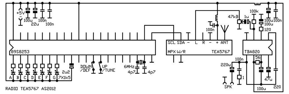
The most important element of the receiver is a tuner module based on TEA5767. It is often used in mp3 players and mobile phones. It provides sensitivity 2uV at very good selectivity, allowing proper reception in high interference environment. The system and several passive elements are placed on a really small (less than 1cm2) board. Microcontroller Atmel 89S8253 from a popular family 51 provides communication with tuner via I2C rail. TBA820 acts as the power amplifier (it is redundant when you create a tuner which operate with external amplifier).
The system should be powered by a voltage of range from 3 to 5V, current consumption is few mA (except the amplifier consumption). The system can be built on universal board, but it is easier to use already made project (more in the attachment to the original thread).
Assembly drawing:
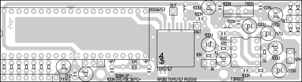
There are also some elements on the board, which were not mentioned on the scheme. They should be put accordingly to the current source you have. Coils are typical low power supply chokes. They can be home made by winding several tens turns of thin wire on a small ferrite core. In particular, they can be omitted by replacing the connections with jumpers.
TBA820 can be powered by voltage less than 15V. If you need greater power (maximum 2W instead of less than 0,5W, as shown in the scheme), just connect the system supply path to higher voltage, for example before the stabilizer.
Modules with TEA5767 are available in different output configurations. You have to identify them and the picture of printed circuit paths should be modified in each case. If a module offers a choice of bus, force I2C mode.
After selecting the program or tuning mode, microprocessor does not work (it is in freeze state), so there are no interferences.
Mounted board from the side of elements:
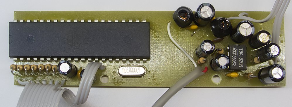
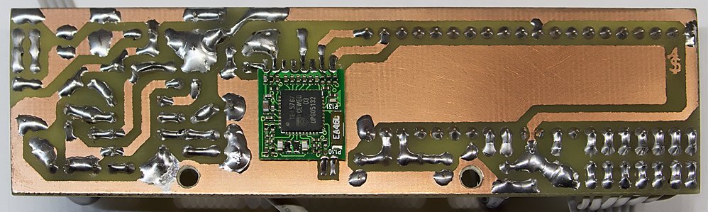
And from the side of print (in the center, you can see module with TEA5767, which after checking the receiver, should be fully shielded by a piece of steel plate):
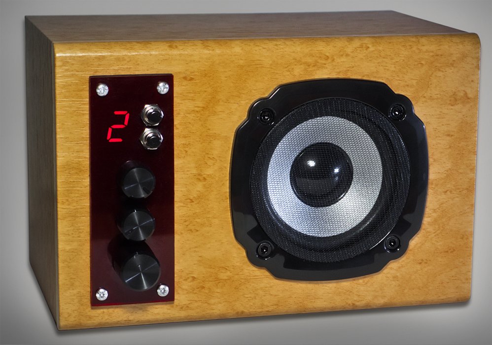
There is a volume control, tone potentiometers (not included in the scheme), a pair or buttons and 7-segment display on the front panel. Electronics is located inside the housing.
The antenna is made of a 15-cm piece of a guitar string, directly soldered to the board. Despite the small size, reception of all available stations is correct.
How it works:
After turning on the receiver, program automatically switches to a default. The program number is shown on the display.
- normal operation mode:
- pressing UP increases the program number
- pressing DOWN decreases the program number
- holding UP switches into programming (tuning) mode
- holding DOWN sets the current program to a default (activating after turning on the receiver)
- programming (tuning) mode
- a miniature of analog scale (the moving point of light) is shown on the display, according to the scheme:

- pressing UP increases the frequency of one step
- pressing DOWN decreases the frequency of one step
- holding UP increases the frequency continuously
- holding DOWN decreases the frequency continuously
- pressing UP while holding DOWN selects the first intermediate frequency
- pressing DOWN while holding UP selects the second intermediate frequency
Changing the intermediate frequency in certain conditions can increase the distance from the noise – for example, if you want to set up a weak station, near which there is a strong station. Type of selected intermediate frequency is shown by the illumination of lack of illumination of G (middle) segment.
After few seconds of inactivity, current frequency is saved in the current program, the display will show the animation and the system will exit the programming mode.
- a miniature of analog scale (the moving point of light) is shown on the display, according to the scheme:
- reset mode
When a receiver is off, hold UP or DOWN button and enable the supply. Then a longer (triple) animation will be displayed, all programs will be set to the frequency of 99MHz, and the first program will be default.
Reset mode is necessary during first activation of the receiver.
Link to original thread (useful attachment) – Realizacja odbiornika radiowego wykorzystująca TEA5767