Vermes
Advanced Member level 4

- Joined
- Aug 2, 2011
- Messages
- 1,163
- Helped
- 0
- Reputation
- 0
- Reaction score
- 0
- Trophy points
- 1,316
- Activity points
- 22,318

This article presents a very simple construction of metal detector.
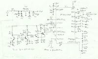
Schematic:

T1 and T2 operate in oscillator circuit. T3 and T4 are Schmitt triggers that are used for forming sinusoidal vibration from the collector T2. Transistors used were 2SC1815Y. Microcontroller operates as high frequency meter – it counts the signal pulses measured while duration of a model pulse. External interrupt INT1 and the counter input T0 are shorted externally. It is the necessary synchronization of measure cycle with measured waveform. It allows the elimination of measurement instability associated with asynchronous occurrence of the first pulse measured in relation to the measuring cycle. Pressing K1 results in start of calibration. Then the average of four successive frequency measurements is calculated. It is the value which is taken as a reference. In subsequent measurements, the microcontroller examines whether the measure generator frequency increased, or increased in relation to the reference frequency. On the basis of that, a buzzer is controlled (with the generator) and appropriately, LEDs. LEDs indicate the increase (D1) or decrease in frequency (D2). Therefore, the detection of ferromagnetic or other metals is indicated. The frequency of blinking the right LED and buzzer beeps is proportional to the oscillator detuning. Detection of detuning is indicated only when it is bigger than set sensitivity which can be set by means of P1. The higher the voltage at the slider is, the lower the sensitivity. The circuit can be theoretically called the simplest AC converter with a single integration. It uses an internal comparator of microcontroller AT89C2051. However, it is not very stable and non-linear. Linearity can be improved using only 0,2 time constant R12, C10. It was calculated than after the time of 440us, voltage on C10 will be 0,9063V. For such voltage, the R11 was calculated. Timer T1 determines the time of model pulse – the gating time. Its interrupt is reported every 62ms. It is also the sampling period of the AC converter. Jumpers Z2, Z3 and Z4 determine the gating time which can be calculated as follows:
MSB LSB
gating time = (Z2 Z3 Z4 + 3)*62ms
If the jumper is on, that means the 0, if off – it means 1. Thus, the maximum gating time is 620ms. To improve the stability of value from AC, the average of measurements is calculated, the number of which is determined by the multiplier given for gating time. Putting on Z5 enables the service mode. This jumper should be put on when the power is on. In this mode, putting on Z2 causes displaying the value of the AC converter (not average) using diodes D1 and D2. Taking off the Z2 causes displaying the measure generator frequency with a resolution of 1kHz (for the convenience of read). The frequency can be calculated in the following way:
frequency [kHz] = (number of D1 blinks) + (number of D2 blinks) *10
While for the value of the AC converter it is:
value of the AC = (number of D1 blinks) + (number of D2 blinks – 1) *100
Start of every measurement display is indicated by buzzer beep. Subsequently D1 blinks, then D2. The range of frequency measurement is 255kHz. When it is exceeded, the buzzer will beep three times and measurement will not be displayed. Putting on Z1 switches the detector to dynamic mode (auto tuning). In this mode, detector does not require to be tuned.
Cylindrical shielded coil is used in this design. Inductance is about 0,9mH. The oscillation frequency of the generator is currently about 54kHz. W1 power switch is coupled with potentiometer P1. The system is powered by stabilizer 78L05 from 9V battery.
The housing was made of floor panels glued together using polymeric glue. Links were additionally reinforced with hobs of toothpicks. Lid was made of plastic from an old printer. The whole was mounted on a universal board.
Pictures:


Software occupies 640 bytes, it was written in Assembler of microcontroller 8051.
How to make a probe:
The probe is quite simple. A very important feature is mechanic rigidity. A minimal (unnoticeable) deformation will be detected as detuning. A disk with a diameter of about 3cm was cut of a piece of floor panel using a hole saw. The thickness of such a panel was 7mm. Then two bigger disks were cut of plastic using the hole saw. After weathered to matt, all the disks were glued centered using polymeric adhesive. For the time of drying, they were screwed with a screw M4. Then the inside of such carcass was covered with aluminum foil. That created the screen. Remember to leave about 1cm for outputs without the shield. The shield must be sealed, and also it can not have more additional holes. Then you can add isolation made of paper. Finally, winding was add and it was protected with tight turns of string. Then another layer of paper and the protruding foil was wrapped inside. Additional strip of foil was added to improve the shield. At the end, the shield output using a piece of wire was pressed to the shield with a string, then paper and external red strip of plastic. When making the coil, remember about the break in the shield.
Link to original thread (useful attachment) - Prosty wykrywacz metali na AT89C2051

