thanhFF
Junior Member level 2
Hi all,
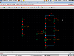
I am doing simulation for simple Colpitss Oscillator, the circuit taken from Thomas Lee book( Chapter 17, page 623). I am using Cadence Virtuoso and SpectreRF to test that. The estimation output frequency was similar to the one discribed in the book (around 60Mhz). However, I dunno how can I get the output voltage based on the equation there. They calculated the output voltage is about 1.4V. But the output voltage i had is very very small.
The NMOS have L = 0.35u, and I changed W based on the number of fingers
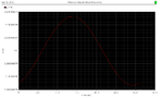
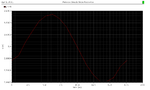
With W = 80u, W/L = 228, the f = 64Mhz, Vout(p-p) = 1.2 uV
With W= 1600u W/L= 4570 the f = 56Mhz, Vout(p-p)= 0.55mv
I change the number of fingers from small to large, to see Vout change, but they are still ver small. In the page 624 they recommended choose W/L =6000 to ensure the start-up condition. I also tried that but the Vout sitll was small.
So my question is why my Vout was so small, I read some equations, but be honest dont understand much, Is it Vout is not related to Vbias and Vdd at all ( in the book Vout just only depends on Ibias,R and capacitivite divide factor)
What I can do to make Vout bigger?
I attached the schematic and result for two cases above
Thanks:-D
I am doing simulation for simple Colpitss Oscillator, the circuit taken from Thomas Lee book( Chapter 17, page 623). I am using Cadence Virtuoso and SpectreRF to test that. The estimation output frequency was similar to the one discribed in the book (around 60Mhz). However, I dunno how can I get the output voltage based on the equation there. They calculated the output voltage is about 1.4V. But the output voltage i had is very very small.
The NMOS have L = 0.35u, and I changed W based on the number of fingers
With W = 80u, W/L = 228, the f = 64Mhz, Vout(p-p) = 1.2 uV
With W= 1600u W/L= 4570 the f = 56Mhz, Vout(p-p)= 0.55mv
I change the number of fingers from small to large, to see Vout change, but they are still ver small. In the page 624 they recommended choose W/L =6000 to ensure the start-up condition. I also tried that but the Vout sitll was small.
So my question is why my Vout was so small, I read some equations, but be honest dont understand much, Is it Vout is not related to Vbias and Vdd at all ( in the book Vout just only depends on Ibias,R and capacitivite divide factor)
What I can do to make Vout bigger?
I attached the schematic and result for two cases above
Thanks:-D