Continue to Site

Welcome to EDAboard.com

Welcome to our site! EDAboard.com is an international Electronics Discussion Forum focused on EDA software, circuits, schematics, books, theory, papers, asic, pld, 8051, DSP, Network, RF, Analog Design, PCB, Service Manuals... and a whole lot more! To participate you need to register. Registration is free. Click here to register now.

logic in circulator for feedback from oscillator

yefj

Advanced Member level 4
Joined
Sep 12, 2019
Messages
1,195
Helped
1
Reputation
2
Reaction score
3
Trophy points
38
Activity points
7,217
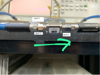
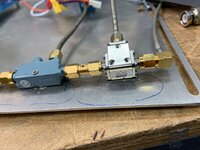
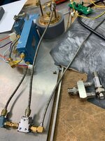
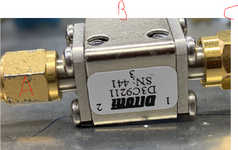
Hello , i have the following system which get a feedback from oscillator from circulator.
As you can see in the lab photos i put power to port A and i need to get the dip in power at port C.
The power input which comes from A and goes into B while the feedback from the resonator is from port C.
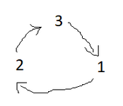
looking at the circulator component i have ports 1 2 3 .
currently its works good i put power to port 2 and i see the "DIP" from port 3 at some frequency range exactly as shown in the article and the attached diagram.
but when i flip ports 2 and 1 i dont see such dip response from port 3
i dont understand few things:
1.why do we inject power to port 2 and not port 1?
Its like a flipped polarity. if i switch the ports and i dont get any dip like as i see when i put power threw port 2.
looking at the diagram from wikipedia why do i see a good dip frequency response from port 2
Thanks.
1703684375756.png


1703683344386.png


1703682770919.png


1703683131176.png
 

Attachments

  • WhatsApp Image 2023-12-27 at 14.41.52.jpeg
    WhatsApp Image 2023-12-27 at 14.41.52.jpeg
    356.5 KB · Views: 50
  • WhatsApp Image 2023-12-27 at 14.39.01.jpeg
    WhatsApp Image 2023-12-27 at 14.39.01.jpeg
    473.2 KB · Views: 48
  • 1703683433105.png
    1703683433105.png
    1.4 MB · Views: 47
  • High_spectral_purity_microwave_oscillator_design_using_conventional_air-dielectric_cavity (3) ...pdf
    563.8 KB · Views: 54
General comment, I don't like to have at least 3 threads discussing operation of cavity stabilized oscillator (not to consider many other threads discussing supporting circuitry). Problem is that you need to refer to other threads or duplicate information.


As the general operation has been discussed in the other threads, I'll restrict my answer to the obvious

Do you have any doubts that circulator direction in circuit diagram from IEEE article could be wrong? If not, you only need to verify that the circulator used in your hardware is connected and working correctly, e.g. with VNA or power meter. Or are you seriously asking if the circuit can work with CCW circulator operation?
 
Signals go clockwise , unless you live upside down or "down under". just kidding.

When matched ports, the differential in permeability acts like a prism to deflect the path in 1 direction for each port.

So if you want the signal out of port 3 then driving from port 1 is backwards "in the traffic circle."

The isolation in the reverse direction must be -36dB at fo from 1 to 3 and after directional couple and adjustable pad, the carrier is further suppressed to 90 dB with the combiner/splitter.

Why are some SMA connectors so banged up? Did you torque them properly too? Better make sure your cables are working as expected with a VNA.
--- Updated ---

Are these rated for Cryogenic temperatures?
 
Last edited:
Hello,I have tested my circulator in network analyzer and i saw the following pattern.
the system acts as shown below.
I measured the signal which passes from port 2 to port 1 while port 3 is open circuit.
when i plug a termination on port 3 i see -25dB of energy passing from port 2 to port 1.
when i plug the resonator i see something in the middle :)
so i understand that the energy ability to pass from port 2 to port 1 linked to the resonance of the resonator at port 3.
How the resonances are linked to the reflection coefficient from port 3?
Thanks.

1703751500517.png


1703751068948.png


1703751110778.png

--- Updated ---

UPDATE:
At resonance the circulator sees 50 Ohm so all energy goes to port 3 instead of port 1.
thats why port 1 is feed back :)
sorry FVM for this question i needed to understand how the circulator and resonator work together.
Thanks.
 

Attachments

  • 1703745943148.png
    1703745943148.png
    1.3 MB · Views: 45
  • 1703747537561.png
    1703747537561.png
    2.2 KB · Views: 43
Last edited:
When I said check circulator operation with VNA, I was thinking about testing the circulator without cavity, terminating the third port with 50 ohm load. Cavity S11 and S21 can be also checked by VNA.
 
  • Like
Reactions: yefj

    yefj

    Points: 2
    Helpful Answer Positive Rating
This seems to be your circulator model:

In the graphs you can see the thru pass measurement from P1 -> P2, with P3 terminated into 50 Ohm.
You can also see that P2 -> P1 is isolated, with P3 terminated into 50 Ohm.

Keep in mind the specified frequency range: 9.2 to 10.5 GHz
 

    yefj

    Points: 2
    Helpful Answer Positive Rating
Keep in mind the specified frequency range: 9.2 to 10.5 GHz
The sweep frequency range of 5 to 11 GHz shown in post #4 involves two problems:
1. Circulator is operated outside useful frequency range.
2. High Q cavity resonance won't be possibly even seen.

I suggest to start with identification of cavity resonance frequency and reflection characteristic using appropriate VNA settings (frequency resolution < 100 kHz) Once you are sure to see the expected resonator behaviour, you can try in combination with circulator.
 
  • Like
Reactions: yefj

    yefj

    Points: 2
    Helpful Answer Positive Rating
If you calibrate each component then you model it and simulate the loop.

This is starting to resemble reverse engineering a concealed radar weapon or bomb detector without prerequisite skills using scavenged components.
 
Last edited:

LaTeX Commands Quick-Menu:

Part and Inventory Search

Welcome to EDABoard.com

Sponsor

Back
Top