electronpower03
Newbie level 6
Hey guys,
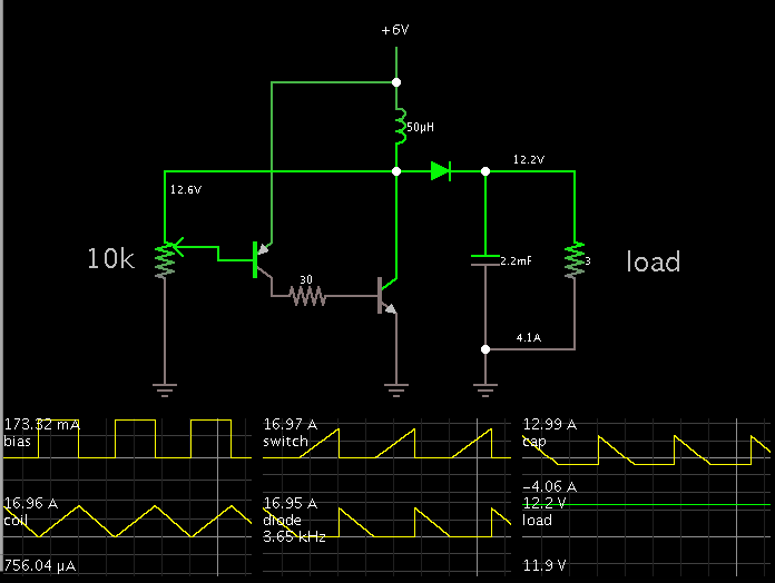
I'm trying to design a dc-dc converter. I've successfully built one that is powered by a 1.5v cell, 9v gen. pupose cell and a 280mAH 9v cell.
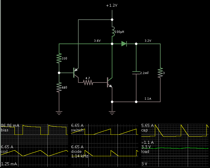
The problem is when I try to power it with high capacity batteries like a lead acid 6v, 4AH cell, it doesn't work! The inductor heats up and the voltage stays at 1v! The same happens when I power it with a 1.2v 3800mAH cell.
Please, do you know why this is? Do you think I should get an inductor with higher current rating and Isat rtaing?
PS: planned out put current is between 4 and 5 amps and I'm using a pnp transistor and an npn Darlington transistor as switch.
I'm trying to design a dc-dc converter. I've successfully built one that is powered by a 1.5v cell, 9v gen. pupose cell and a 280mAH 9v cell.
The problem is when I try to power it with high capacity batteries like a lead acid 6v, 4AH cell, it doesn't work! The inductor heats up and the voltage stays at 1v! The same happens when I power it with a 1.2v 3800mAH cell.
Please, do you know why this is? Do you think I should get an inductor with higher current rating and Isat rtaing?
PS: planned out put current is between 4 and 5 amps and I'm using a pnp transistor and an npn Darlington transistor as switch.
")