Continue to Site

Welcome to EDAboard.com

Welcome to our site! EDAboard.com is an international Electronics Discussion Forum focused on EDA software, circuits, schematics, books, theory, papers, asic, pld, 8051, DSP, Network, RF, Analog Design, PCB, Service Manuals... and a whole lot more! To participate you need to register. Registration is free. Click here to register now.

DC to DC conversion problem

Status
Not open for further replies.

electronpower03

Newbie level 6
Newbie level 6
Joined
Jan 22, 2013
Messages
14
Helped
0
Reputation
0
Reaction score
0
Trophy points
1,281
Visit site
Activity points
1,427
Hey guys,

I'm trying to design a dc-dc converter. I've successfully built one that is powered by a 1.5v cell, 9v gen. pupose cell and a 280mAH 9v cell.

The problem is when I try to power it with high capacity batteries like a lead acid 6v, 4AH cell, it doesn't work! The inductor heats up and the voltage stays at 1v! The same happens when I power it with a 1.2v 3800mAH cell.

Please, do you know why this is? Do you think I should get an inductor with higher current rating and Isat rtaing?

PS: planned out put current is between 4 and 5 amps and I'm using a pnp transistor and an npn Darlington transistor as switch.

Post circuit first. Usually DC/DC StepUp designs have some input voltage range.
 
So your bigger batteries can supply real current for the ON times that appear to be too long for the small size inductor you have chosen.

Bigger uH choke with bigger peak current rating, and check your circuit to see if the freq is appropriate.
 
  • Like
Reactions: Orson Cart

    Orson Cart

    Points: 2
    Helpful Answer Positive Rating
    V

    Points: 2
    Helpful Answer Positive Rating
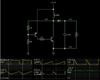
The schematic's attached.

can you please advise the formular to calculate the frequency?
 

Attachments

  • conv.jpg
    conv.jpg
    573.9 KB · Views: 153

This is a hysteresis-driven configuration, controlled by 2 transistors. I have not seen this one before.

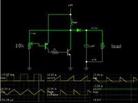
And it works! Here is a screenshot of my simulation. Supply is 1.2V, output is 3V at 1A:


Notice the low-ohm resistor at the transistor bias. If this is too large, then the transistor will not turn on sufficiently, and it will not pull sufficient current through the coil.

The transistor needs to pass several amperes, and to deliver that amount to the output stage.

Whatever current you want out, the peak waveform through the coil needs to be several times that.

It is important to observe the inductive saturation current spec. As you know, this is different from the overheat current spec. You can use an overheat current spec of 4A for the coil, even though the peak current rises to 6.65 A.

If you wish to get more power out, then your power source must deliver adequate current. The resistor network at the left may need to be adjusted. While experimenting I used a potentiometer.

This link will open the falstad.com/circuit website, load my schematic above, and run it on your computer:

https://tinyurl.com/a5dezvc

You can change values, by right-clicking on a component and selecting Edit.
 

    Orson Cart

    Points: 2
    Helpful Answer Positive Rating
    V

    Points: 2
    Helpful Answer Positive Rating

    tpetar

    Points: 2
    Helpful Answer Positive Rating
Thanks.

I've observed from my use of the circuit ( which probably cannot be simulated), that the ouput voltage and current depend on the input current.

Some of the input current is what's converted to voltage. So, output voltage is limited by input current and other factors like the type of npn

transistor used (Darlingtons provide more).

Since some of the input current is used up in the conversion process, I decided to opt for a higher capacity cell. A 7000mAH should do it, right?

There should still be surplus current for an output of 4-5amps with a 7000mAH cell, right?

Thanks for your tips guys!

I'll try and look for an inductor that can handle the current. Most of the once found on coilcraft have reduced inductance values, sometimes down to nano Henrys! I'll keep looking and experiment as suggested by Bradtherad.

Thanks, guys! More tips, please! :)

- - - Updated - - -

Thanks.

I've observed from my use of the circuit ( which probably cannot be simulated), that the ouput voltage and current depend on the input current.

Some of the input current is what's converted to voltage. So, output voltage is limited by input current and other factors like the type of npn

transistor used (Darlingtons provide more).

Since some of the input current is used up in the conversion process, I decided to opt for a higher capacity cell. A 7000mAH should do it, right?

There should still be surplus current for an output of 4-5amps with a 7000mAH cell, right?

Thanks for your tips guys!

I'll try and look for an inductor that can handle the current. Most of the once found on coilcraft have reduced inductance values, sometimes down to nano Henrys! I'll keep looking and experiment as suggested by Bradtherad.

Thanks, guys! More tips, please! :)
 

Since some of the input current is used up in the conversion process, I decided to opt for a higher capacity cell. A 7000mAH should do it, right?

There should still be surplus current for an output of 4-5amps with a 7000mAH cell, right?

I think I've heard a 1.5V D cell can put out 10 or 20 A.

If you are aiming for 12V output at 4A, then a good power source is your lead acid 6v, 4AH battery.

To show that your circuit can be simulated (and to be helpful)...


This version delivers your desired 4A output.
Notice that it needs to draw over 8A average from the power source. Peaks are 17 A. That is the saturation spec for your coil.

The bias resistor determines how much current goes through the NPN, thus determining power output.

Your 6V 4AH battery will last under 1/2 hour.
A single 1.5V D cell might be 4AH. It might last a few minutes, if you were to draw 16A peaks of current.
 

Thanks, guys!

Apparently, the circuit not quite efficient...still needs to be tweaked to get power for lower current used up.

BTW, how's the switching frequency calculated? Anyone knows?
 

Thanks, guys!

Apparently, the circuit not quite efficient...still needs to be tweaked to get power for lower current used up.

BTW, how's the switching frequency calculated? Anyone knows?

A suitable range of switching frequency is based chiefly on your coil's Henry value.
Additional factors contribute, of course.

Below is a thread about power converters. See my posts which contain links to interactive learning tools. There is one simulation depicting the basic concepts of a boost converter.

https://www.edaboard.com/threads/268178/
 

    V

    Points: 2
    Helpful Answer Positive Rating
Hey all!

I've used inductors with higher Isats and they worked!

So, I've been able to boost the 6v to about 63v!!

Well, now that I've got a power source between. 6 and 63v, I thought I'd use it to power my laptop.

My adpter says 19v. I clamped the output of the converter at 19. The power LED did light, alright, but on
Turning on the laptop? It goes off!

I observed the converter's voltage droped when loaded!

Why is this? There's over 4 amps of current to spare after conversion! So why isnt the laptop powered?

NB: I tried to use a regulator, twas the same thing! This time around I clamped the converter's voltage at 30 and outputed 19 from the regulator...why isn't the laptop getting powered?

Electronpower03
 

The laptop computer may accept only a narrow volt range from your power supply, and a stable waveform, in order to turn on.

This makes it chancey, whether you can use it as the sole power source.

Try this experiment with your power supply...

Add the battery pack, to stabilize the volt level and waveform.

Soon after the computer turns on, it will draw down the battery enough that it will start to charge. It should start calling for current from your power supply. (A light should turn on, to indicate when the laptop is charging.)

By watching the volt level, you will find out whether your power supply can keep up with demand.
 

Status
Not open for further replies.

Similar threads

Part and Inventory Search

Welcome to EDABoard.com

Sponsor

Back
Top