kaunasLT
Newbie
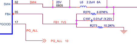
Looking at a TI application note they have placed the filter cap parallel to the resistor on the "high side" (see attached picture).
the capacitor would create a low impedance path for high frequency and almost have no voltage drop, wouldnt the high frequency noise then be sampled at the feedback node?
why not place the cap parallel across the lower side resitor such as when the high frequency of the switching noise see a low impedance to ground and the feedback node can measure low frequency DC to adjust the output?
Im asking this because I was playing around creating a DIY buck and have in my design placed the cap to give a low impedance to ground and would from there derive a transfer function i can further compensate digitally using PID.