Continue to Site

Welcome to EDAboard.com

Welcome to our site! EDAboard.com is an international Electronics Discussion Forum focused on EDA software, circuits, schematics, books, theory, papers, asic, pld, 8051, DSP, Network, RF, Analog Design, PCB, Service Manuals... and a whole lot more! To participate you need to register. Registration is free. Click here to register now.

CMOS dc -dc convertor design M.E project

Status
Not open for further replies.
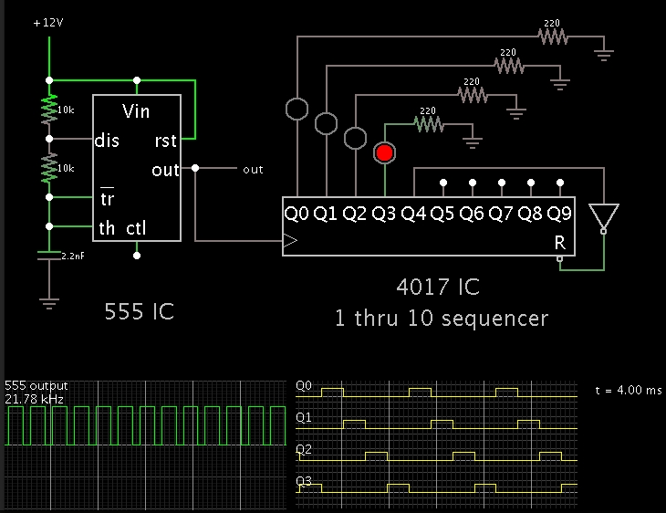
The multiphase converter needs interleaving for phases
so can anybody suggest me circuitry for giving a signal with phase shift to each converter
I require to introduce 90,180,270 degree phase shift
please help
 

Can someone suggest me a way to convert the voltage across capacitor C5=15.517n into a current so that i can then give it to a comparator to compare it with a reference.
Also please a ckt that allows to introduce phase shifts of any degree
Please do help
 

Attachments

  • fil.png
    fil.png
    29.8 KB · Views: 69

Please help me with this ckt
I am implementing average current mode control on this converter. I am using inductor dcr current sensing
Pleasse suggest how i can convert the voltage across the capapcitor in parallel to the inductor DCR into current so i can give it to the pwm generator
 

Attachments

  • SCHEMATIC1 _ PAGE1.pdf
    14.1 KB · Views: 78

Can someone suggest me a way to convert the voltage across capacitor C5=15.517n into a current so that i can then give it to a comparator to compare it with a reference.

I have seen this done by installing either:
* a 2-resistor network (one with a high ohm value, the other with a small ohm value) between output and ground
* a single resistor (small ohm value) between the load and ground.

That is the general concept. You'll need to consult datasheets to get the particulars.

Also please a ckt that allows to introduce phase shifts of any degree

This gets complex. It starts to look as though a microcontroller is the easy way to distribute 4 pulses at the proper sequence, and for the proper lengths of time. By changing just one variable, you can change all 4 duty cycles.

The schematic below is simpler, but it will work only if you want a 25% duty cycle at each of the four converters.


You can also get 50% duty cycle on each converter, if you overlap each output to two loads, with a staggered effect.

If you want to adjust duty cycles, you will need four one-shots. You will need to tinker with all 4 one-shots independently, to get the duty cycles right.

There may be a better solution.
 

I have seen this done by installing either:
* a 2-resistor network (one with a high ohm value, the other with a small ohm value) between output and ground
* a single resistor (small ohm value) between the load and ground.

That is the general concept. You'll need to consult datasheets to get the particulars.
How to use a differentiator to get the current across the capacitor. Also in this case the voltage is differential and not single ended
 

How to use a differentiator to get the current across the capacitor. Also in this case the voltage is differential and not single ended

We can measure volt level across a capacitor. Or we can measure current going through a capacitor. I cannot figure out which you want to do. C1 (in your post #63) has its lower terminal connected to ground. (We'll ignore the low ohm resistor.) Its charge level can be measured more or less directly.

Now I see you asked previously about C5. I believe it does not influence operation very much, because it is in series with R27, which is 20k, a relatively high value. It looks like it could be a snubber network, but I'm not sure a snubber is needed here.

I also believe M1 is oriented the wrong way. Current is able to flow up through the diode whether the mosfet is biased on or off. Things will be easier if you substitute a diode at this stage while you are developing the circuit.

- - - Updated - - -

Paragraph 3 above is in view of the fact that this is a buck converter. Its operation has current flowing up through M1 during the second half of the cycle.
 

Now I see you asked previously about C5. I believe it does not influence operation very much, because it is in series with R27, which is 20k, a relatively high value. It looks like it could be a snubber network, but I'm not sure a snubber is needed here.

The R and C in parallel with the inductor are according to the Inductor DCR current sensing method.I want to get the average current so that i can compare it with the reference current from the voltage loop(want to implement average current mode control).
The voltage across C5 is same as R28 by matching the time constants(post #63). I want to extract the current now

You can calculate current through C5 by measuring voltage across R27. It will not be the average value. To find the average, you must take a lot of readings, say ten per cycle. Then average them. Or average their absolute amplitudes.

This could be an area where the spec sheet only tells you a few things, but not everything. I suppose you will need to find someone who has done the exact same thing with the same IC. Or else you will need to use your ingenuity.

Is this approach technically correct. The voltage across the capacitor(15.517n) in parallel ti L1 is Il*R28(this is achieved by matching the time constants).
So if the amplifiy this voltage using a differntial amplifier with a gain of 1/R28 i should get the current Il
 

Attachments

  • SCHEMATIC1 _ PAGE1.pdf
    15.2 KB · Views: 72

Is this approach technically correct. The voltage across the capacitor(15.517n) in parallel ti L1 is Il*R28(this is achieved by matching the time constants).
So if the amplifiy this voltage using a differntial amplifier with a gain of 1/R28 i should get the current Il

The 1k resistor to ground will greatly attenuate current coming through the 20k resistor (R27).

I can't say how well an op amp will work with a 2V supply.

My simulation shows that C5 will have less than 1 mA going through it.
 

The 1k resistor to ground will greatly attenuate current coming through the 20k resistor (R27).

I can't say how well an op amp will work with a 2V supply.

My simulation shows that C5 will have less than 1 mA going through it.

What will be the effect if i convert the differential voltage across C5 into a single ended output ?
Will that give me correct current ?

- - - Updated - - -

The 1k resistor to ground will greatly attenuate current coming through the 20k resistor (R27).

I can't say how well an op amp will work with a 2V supply.

My simulation shows that C5 will have less than 1 mA going through it.

This is a new circuit that i tried
When i try to tap the differential voltage across C5(capacitor parallel with inductor DCR) the voltage acoss it and DCR no longer remain same. why ?
I tried a current sense amplifier MAX4372F with a gain of 50V i.e my input gets multiplied by that much i think
now i require a the inductor current at the output which is 10A. I tried connecting a resistor at the output of the current sense amplifier and found that the voltage also changes based on the connected resistor which should not happen. Where am i going wrong here ?
 

Attachments

  • SCHEMATIC1 _ PAGE1.pdf
    15 KB · Views: 68
  • MAX4372-MAX4372T.pdf
    964.7 KB · Views: 73

What will be the effect if i convert the differential voltage across C5 into a single ended output ?
Will that give me correct current ?

C5 has current going one way through it and then the other way.
You can try measuring voltage across it but that will not necessarily tell you about current flow through it.

This is a new circuit that i tried
When i try to tap the differential voltage across C5(capacitor parallel with inductor DCR) the voltage acoss it and DCR no longer remain same. why ?
I tried a current sense amplifier MAX4372F with a gain of 50V i.e my input gets multiplied by that much i think
now i require a the inductor current at the output which is 10A. I tried connecting a resistor at the output of the current sense amplifier and found that the voltage also changes based on the connected resistor which should not happen. Where am i going wrong here ?

I'm sorry, but I'm not familiar with the MAX4372 IC. The datasheet says it is designed to measure the differential V across a small resistance. I believe it will be more useful if you use it on R28 which is directly in line with the coil.

This is a complicated application of electronics. In order to set up the proper measuring scheme, you will need to get familiar with simpler concepts. Such as to experiment with the MAX4372 on simpler circuits. Use an oscilloscope to find out what goes on with C5.

Question: Do you still have your original goal to build a power converter? Is C5 important in some way that you are aware of?
 

C5 has current going one way through it and then the other way.
You can try measuring voltage across it but that will not necessarily tell you about current flow through it.


I'm sorry, but I'm not familiar with the MAX4372 IC. The datasheet says it is designed to measure the differential V across a small resistance. I believe it will be more useful if you use it on R28 which is directly in line with the coil.

This is a complicated application of electronics. In order to set up the proper measuring scheme, you will need to get familiar with simpler concepts. Such as to experiment with the MAX4372 on simpler circuits. Use an oscilloscope to find out what goes on with C5.

Question: Do you still have your original goal to build a power converter? Is C5 important in some way that you are aware of?
converter

Yes my goal is still the buck converter. I have implemented the voltage mode control and want to implement current mode control. Thats why i need the inductor current. Here i can implement peak/average current mode control. Had found out that average current mode control has its advantages over peak current mode control.So i choose a loss less technique of current measurement (The inductor DCR current sense using a RC). So when i match the time constants L/DCR and RC the voltage across the capacitor and DCR will be the same IL*DCR. The capacitor is needed as in actual circuit the DCR wont be available to sense the current across it, a sense resistor would have to be added. So according to me the capacitor is important in the practical case as a measure of current. The voltage across it will be directly proportional to the inductor current IL. So that's why i used the current sense amplifier as it will produce a voltage with a gain of 50*input voltage
In proper working the current sense amplifier should have outputed a fixed voltage for a fixed input, but it is not doing so. Its output is changing based on the resistor i connected.Without getting the current i cant move forward with that.
So need help with it
 

Yes, I see how it works now. Here is a simulation:


It has only the essential components for a buck converter. Most of the values are from your latest schematic (post #71).

As you stated, the V across C5 is proportional to A through the coil. C5 has the more positive polarity at the left. Only a few mV appears across it. This amount seems rather low for a device to detect.

I find that R27 needs to be tailored to the coil resistance. When I increase coil resistance to .01 ohm, the capacitor waveform is lifted on a DC component. I must then reduce R27 in order to restore proportional action.

I can't predict what will be the real-life resistance of your coil.

Your insights are very valuable to me
I found that the IC MAX4327 was configured by me in the wrong manner. It has to be connected across a shunt resistor and not across a capacitor as i had connected, so it was giving me wrong results. Still,i need a way to extract the current information
 

Need a operational amplifier with stable gain sligtly above 500Khz for my current sensing purpose
Kindly suggest me one
 

Need a operational amplifier with stable gain sligtly above 500Khz for my current sensing purpose
Kindly suggest me one

Op amp specs have a gain-bandwidth product. It's calculated as gain x bandwidth.
You can have lots of gain, but at low frequencies.

Or you can have a large bandwidth, but low gain.

Cheap op amps have a lower gain-bandwidth product. You'll need a high-performance op amp, to give you much gain at 500 kHz.

You'll need to look over spec sheets. Or, consider starting a new thread on this question.
 

Multiphase buck converter

Wanted some guidance here
Was looking into Power Mosfets with low Rdson for my converter and found TI has good ones
should i choose the mosfets with the lowest on resistance or should have moderate Rdson ?
Secondly i see that the MOSFETs come in SON packages, and as what i have seen they do not have protruding leads like a DIP package
Will a rookie like me be able to solder them on a pcb with a soldering iron ? or should i go for a different package ?
https://www.ti.com/lsds/ti/power-management/n-channel-mosfet-transistor-products.page
 

If they are carrying 10A, you want the mosfets to go to as low RON as they can.

Example, if the RON is 0.1 ohm...
Then it develops 1 V drop when it carries 10A.
This calculates to 10W wasted as heat. The mosfet should probably have a heatsink attached.

But if RON is 0.01 ohm...
Then it develops 0.1 V drop at 10A.
This calculates to 1W wasted as heat. No heatsink is needed.
 
Please help me out with this mosfet
Why does it have multiple sources and drains ?
 

Attachments

  • NTMS4920NR2G.pdf
    119.9 KB · Views: 67

Status
Not open for further replies.

Part and Inventory Search

Welcome to EDABoard.com

Sponsor

Back
Top