Continue to Site

Welcome to EDAboard.com

Welcome to our site! EDAboard.com is an international Electronics Discussion Forum focused on EDA software, circuits, schematics, books, theory, papers, asic, pld, 8051, DSP, Network, RF, Analog Design, PCB, Service Manuals... and a whole lot more! To participate you need to register. Registration is free. Click here to register now.

Can I use a CC for RF Impedance matching?

Status
Not open for further replies.

aht2000

Junior Member level 3
Joined
Apr 18, 2015
Messages
30
Helped
0
Reputation
0
Reaction score
2
Trophy points
1,288
Activity points
1,664
The output of the SA612 mixer is 1500 ohm as per datasheet, this output should go into a 10.7MHz ceramic filter which input and output impedance is 330 ohm. This is part of an FM receiver. If I want to have a kind of impedance matching between the two to maintain the power transfer and "I guess a good SNR", I tried to use an online calculator for a pi network with a Q of 10.7Mhz/300KHz(BW) = 35 and the value of the L is 935.3 nH which will be physically large.


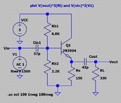
Can I use a common collector setup to match the high to low impedance based on a 2N3904. The size will be smaller and all in SMD but I am not sure about how to calculate the Q for such setup if it acceptable as a solution in the first place. I am attaching the ltspice simulation I used.
 

Attachments

  • CC Mixer Imp Match 1500 - 330 ohm.zip
    758 bytes · Views: 110
  • 1500-330 ohm imp matching.JPG
    1500-330 ohm imp matching.JPG
    120 KB · Views: 131

You can do most simulations with LTspice as well, probably slightly less comfortable. RF transistor SPICE models, e.g. BFR93 can be imported.
 

As a freelance, no student, I have no access or way for even trial versions of ADS or Microwave office to run similar RF simulation. I am mainly using LT Spice but obviously not an RF oriented simulator.

Any recommended free or reasonably priced real RF simulation package?

You can do almost everything which ADS does..
 

The BJT with its Cbe and C2 (emitter cap to gnd) can potentially give negative resistance looking from the base terminal. In fact, it is one of the types of of negative resistance circuits which is built for designing oscillators. Just using a high enough value for C2 (like few nF of cap or even higher if possible) should avoid oscillations or negative resistance.
I followed your proposal, and replaced the C2 with 10nf, and as you advised, the negative resistance disappeared. Of course the input impedance dropped to 400ohm, so no more 1500 ohm input impedance but as I understood from a recent response, I need to replace the transistor with a real RF one, which I did and as per LTSpice got me back the 1500 ohm input impedance that I am looking for.
--- Updated ---

You can do most simulations with LTspice as well, probably slightly less comfortable. RF transistor SPICE models, e.g. BFR93 can be imported.

Looks like is about Miller effect, due to improper transistor used (2N3904).
Placing the same schematic from post #4 in a real RF simulator, and using an RF transistor (BFR93), I got decent S11 (at 1.5k) and S22 (at 330 ohms). Stability K factor is above 1 for a wide frequency range.
Adjusting the DC bias of the transistor gets even better results.
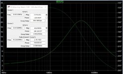
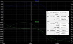
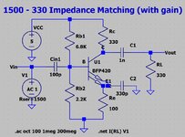
I did with a BFP420 (attached its .asy and .lib), and the LTSpice results look promising. Please see attached Z11 and Z22. However, looking at S21, the gain peak is at 50MHz, I tried to increase C2 to move the peak to the left, it does but it gets flatter, and at C2=10nf, the input impedance is reducing (expected). Is there a way to maximize the gain at 10.7MHz, and still keep the Z11 and Z22 unchanged at the same frequency?

I know that this transistor has gain far beyond this frequency range, and I am happy with the bell shape curve for S21 as to avoid unwanted oscillation at high frequency, but I am not able to identify which part of the circuit is responsible for taking the gain down above 50MHz??
 

Attachments

  • 1500-330 ohm imp S21 BFP420.JPG
    1500-330 ohm imp S21 BFP420.JPG
    224.1 KB · Views: 94
  • 1500-330 ohm imp Z11 Z22 BFP420.JPG
    1500-330 ohm imp Z11 Z22 BFP420.JPG
    281.7 KB · Views: 92
  • 1500-330 ohm imp BFP420.JPG
    1500-330 ohm imp BFP420.JPG
    140.4 KB · Views: 92
  • BFP420.zip
    19 KB · Views: 77
Last edited:

The circuit has high-pass behaviour by C2 and low-pass behaviour by miller capacitance in combination with the source impedance. If you want higher gain at lower frequencies, you need to increase C2. As previously discussed, large signal behaviour of the receiver is degraded by having too much gain before the IF filter.
 

Status
Not open for further replies.

Part and Inventory Search

Welcome to EDABoard.com

Sponsor

Back
Top