Continue to Site

Welcome to EDAboard.com

Welcome to our site! EDAboard.com is an international Electronics Discussion Forum focused on EDA software, circuits, schematics, books, theory, papers, asic, pld, 8051, DSP, Network, RF, Analog Design, PCB, Service Manuals... and a whole lot more! To participate you need to register. Registration is free. Click here to register now.

settling time and propogation time delay simulation

Status
Not open for further replies.

Junus2012

Advanced Member level 5
Joined
Jan 9, 2012
Messages
1,552
Helped
47
Reputation
98
Reaction score
53
Trophy points
1,328
Location
Italy
Activity points
15,235
Dear friends

I an simulating the total settling time of t he operational amplifier. I am connecting it as a buffer and I apply an input pulse. I have no problem to measure the slew rate, but when I tell the calcultaor to calcultae the settling time it take several periods of my signal, why ??

I also would ask you in case if I want to measure the linear settling time under the small signal condition, how much should I apply step voltage so that that the op-amp is not slewing ? also how to measure the propogation time delay ??

thank you in advance
 

Hi Senan=Junus ;-)

for the large signal mode, perhaps **broken link removed** may be helpful.

Scroll down to FO4 Inverter Delay Simulation

erikl
 
Dear friends
I an simulating the total settling time of t he operational amplifier. I am connecting it as a buffer and I apply an input pulse. I have no problem to measure the slew rate, but when I tell the calcultaor to calcultae the settling time it take several periods of my signal, why ??
I also would ask you in case if I want to measure the linear settling time under the small signal condition, how much should I apply step voltage so that that the op-amp is not slewing ? also how to measure the propogation time delay ??
thank you in advance

Of course, I don`t know which calculator you are using and if it is able at all to calculate the settling time. But you are right that sometimes the settling time is overshadowed by the slew rate.
The settling time is a parameter that involves no non-linear effect and, thus, the input signal must be small enough not to cause slewing - that means not to saturate the first stage of the opamp.
I think, in simulation it is not a problem to use input levels of - let`s say - 0.1mV or so.

- - - Updated - - -

As an outcome of some similar investigations I have some simulation results at hand for the opamp type AD845 which may be interesting for you:

* Input step 1mV: Output ringing with settling time (1%) approx. 0.8µs (gain of 2) and 0.3µs (gain of 5),
* Input step 1V: Output rise time (slew rate effect) for a gain of 10: 0.9µs.
 
nice to remember my old name Erikl :)

- - - Updated - - -

Of course, I don`t know which calculator you are using and if it is able at all to calculate the settling time. But you are right that sometimes the settling time is overshadowed by the slew rate.
The settling time is a parameter that involves no non-linear effect and, thus, the input signal must be small enough not to cause slewing - that means not to saturate the first stage of the opamp.
I think, in simulation it is not a problem to use input levels of - let`s say - 0.1mV or so.

- - - Updated - - -


As an outcome of some similar investigations I have some simulation results at hand for the opamp type AD845 which may be interesting for you:

* Input step 1mV: Output ringing with settling time (1%) approx. 0.8µs (gain of 2) and 0.3µs (gain of 5),
* Input step 1V: Output rise time (slew rate effect) for a gain of 10: 0.9µs.


Hello All

in the first part of my problem I was simulating the total settling time which consist of (Propagation delay+ S.R + linear settling) but as I mentioned the calculator was taking some periods, perhaps it just come to my mind , i must apply only a zero to one or one to zero rather than applying a periodic input pulse signal then the calculator will be confused.

for the only linear settling time simulating I did as you suggested me to apply like 0.1 V, but isnt this time has also a part of the linear response time (propagation time delay )??? how to separate each other??

third, I also asked this question before and perhaps you answered me
why we consider the unity gain buffer is the worst case settling time and S.R measurement ? I know this represent the largest feedback and it is the worst case stability but hoe that effect the transient behavioural. I read from Jouhn Marting book that the linear settling time is inverse proportional to the closed loop bandwidth, which mean the unity gain buffer has the fastest linear settling time not the worse. in addition that I read in one paper that there is no difference to measure S.R with open or closed loop because it depend on the charging discharging current

I am sorry for my long post but I dont know how to make shortcut :)

thank you again
 

Hello Junus (I guess this is your Italian name, Senan was your German name, isn't it? ;-) ),

I'll try and explain this apparent contradiction:

I read from Jouhn Marting book that the linear settling time is inverse proportional to the closed loop bandwidth, which mean the unity gain buffer has the fastest linear settling time not the worse.

This is only true if the phase margin can be kept above 60° within the whole bandwidth, and for all considered closed loop gains. It guarantees few overshoot and no ringing. As you probably know, this is as more difficult as lower the closed loop gain, and, by this, as higher the bandwidth is.


… why we consider the unity gain buffer is the worst case settling time and S.R measurement ? I know this represent the largest feedback and it is the worst case stability but hoe that effect the transient behavioural.

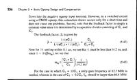
This is valid for phase margins < 60° , where large overshoot and ringing will occur, s. the foll. comparison from Razavi's book:


Considering an opAmp, whose phase margin falls below the 60° limit at low closed loop gains - as smaller the closed loop gain, as lower its phase margin will be, and as heavier overshoot and ringing it will create. By this, it takes longer for the output signal to stay in the required tolerance interval - hence the unity gain mode will create the longest settling time, s. the figure from the foll. page:
settling_time.png
 
I read from Jouhn Marting book that the linear settling time is inverse proportional to the closed loop bandwidth, which mean the unity gain buffer has the fastest linear settling time not the worse. in addition that I read in one paper that there is no difference to measure S.R with open or closed loop because it depend on the charging discharging current

I am sorry for my long post but I dont know how to make shortcut :)

thank you again

Are you sure that the mentioned book refers to the settling time ? I think, the rise time will be inverse prop. to the bandwidth.
Regarding the slew rate, the loop must NOT be open. The reason is as follows: For testing the SR the first stage only must be saturated without saturating the following stages - in particular the output stage.
This can be accomplished with heavy feedback only and the effect is the following:
The input step (e.g. 1 Volt) drives the first stage into saturation - until the feedback action "slowly" (that is the slew effect) brings the whole circuit back to the linear operation.
 
Are you sure that the mentioned book refers to the settling time ? I think, the rise time will be inverse prop. to the bandwidth.

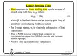
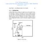
Here's a slide from a lecture* by D.A. Johns & K. Martin where they actually claim this for settling time, but precisely for linear settling time, which, I think, complies with my above statement for phase margins ≧ 60° (no ringing):
linear_settling_time.png * "Advanced Current Mirrors and Opamps", University of Toronto, 1997
 
Here's a slide from a lecture* by D.A. Johns & K. Martin where they actually claim this for settling time, but precisely for linear settling time, which, I think, complies with my above statement for phase margins ≧ 60° (no ringing):
View attachment 83948 * "Advanced Current Mirrors and Opamps", University of Toronto, 1997

Hi Erik,

reference is made to your statements in post#5:

...if the phase margin can be kept above 60° ............. It guarantees few overshoot and no ringing.

I think, in case there is no overshoot and no ringing there is not much difference between settling and rise time.
More than that, I must confess that - up to now - I didn`t hear about the term "linear" settling time.
To my understanding, the term "settling time" always applies to linear systems only. But I may be in error because it´s "only" a matter of definition.
 

Hi Lutz,

I think, in case there is no overshoot and no ringing there is not much difference between settling and rise time.
Yes, I think the same.

... up to now - I didn`t hear about the term "linear" settling time.
To my understanding, the term "settling time" always applies to linear systems only.
Same for me. If I interpret their above slide correctly, I'd think the wording "linear" in Johns/Martin's term "linear settling time" refers to an output response without ringing - but this is just guesswork.

erikl
 

Hello guys
thanx a lot for your active participation
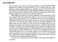
the linear settling time is the final part of the settling time when the op-amp leave the large signal condition after the slew rate as you can see in t he attached file, John Marting and Holberg also differentiated between the linear and non linear settling time.

later I will attache you the page Nr from the both references with the examples from John Martin

- - - Updated - - -

As I understand from you

the rule of the larger closed loop bandwidth will lead to better settling time if only the phase margin is greater than or equal to 60

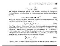
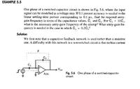
any way as I said before, i will show you the examples from John Martin, when he solved to find the settling time from the closed loop bandwidth, he didnt consider the phase margin.
in sense ,I agree with you both because the phase margin has an effect on the time behavioural as from the pics of Behzad applied by Erikl
 

Attachments

  • 466359863287538299597392756AN359.pdf
    632.2 KB · Views: 64
  • 466359863287538299597392756AN359.pdf
    632.2 KB · Views: 52

Hi Junus,
so it seems you have found the answer by yourself.
Thanks for the AD application note. I did not know about it - up to now.
 

I must thank you all you guys,
again I forgot to appload the John Examples :) but I would dó it latrer :)

Regards

Hi Junus,
so it seems you have found the answer by yourself.
Thanks for the AD application note. I did not know about it - up to now.
 

hello

I attached you a parts from John Martin regarding the linear settling time
the attachments are in sequence


have fun :) and thank you
 

Status
Not open for further replies.

Part and Inventory Search

Welcome to EDABoard.com

Sponsor

Back
Top