Continue to Site

Welcome to EDAboard.com

Welcome to our site! EDAboard.com is an international Electronics Discussion Forum focused on EDA software, circuits, schematics, books, theory, papers, asic, pld, 8051, DSP, Network, RF, Analog Design, PCB, Service Manuals... and a whole lot more! To participate you need to register. Registration is free. Click here to register now.

Wide range LC oscillator with constant amplitude

Status
Not open for further replies.

neazoi

Advanced Member level 6
Joined
Jan 5, 2008
Messages
4,123
Helped
13
Reputation
26
Reaction score
15
Trophy points
1,318
Location
Greece
Activity points
36,955
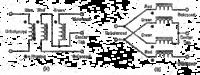
Hi, I would like to try the oscillator in Fig. 8 of the attached article.

What options do I have to achieve a -15v for VCC for this circuit?
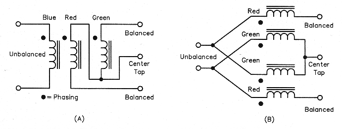
Also, can I connect the output to such a transformer


(above diagram found at: http : // www . robkalmeijer . nl/ techniek/electronica/radiotechniek/hambladen/qst/1993/12/page32/fig06.png]

to get a balanced output? (in order to drive a balanced mixer).
 

Attachments

  • 515-158.pdf
    1.5 MB · Views: 89
Last edited by a moderator:

I also would like to know which way the FETs are connected (although not critical)?
Is the drain towards the ground and the source towards the negative, or the other way round?
 

Source is at the top in the schematics. Note the supply rail is negative with respect to ground.

The baluns will work but be careful to ensure they are not self resonant near the oscillator frequency or they may distort the signal or worse, become the tuning element themselves.

Brian.
 
  • Like
Reactions: neazoi

    neazoi

    Points: 2
    Helpful Answer Positive Rating
Source is at the top in the schematics. Note the supply rail is negative with respect to ground.

The baluns will work but be careful to ensure they are not self resonant near the oscillator frequency or they may distort the signal or worse, become the tuning element themselves.

Brian.

Thanks brian.
It is an interesting vfo isn't it? I will test it in a few weeks to see how it works. The capacitors are of relatively low values, so NP0 ones could be used. This will allow me to judge the circuit frequency drift without it being affected by the components ppm much.

Do you believe that with a suitable LC, it will be stable enough for SSB operation?

Do you believe that this oscillator could also work using a ctystal in place of the LC?
 

Status
Not open for further replies.

Part and Inventory Search

Welcome to EDABoard.com

Sponsor

Back
Top