Welcome to our site! EDAboard.com is an international Electronics Discussion Forum focused on EDA software, circuits, schematics, books, theory, papers, asic, pld, 8051, DSP, Network, RF, Analog Design, PCB, Service Manuals... and a whole lot more! To participate you need to register. Registration is free. Click here to register now.
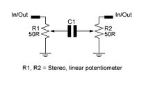
I wonder if this small variable attenuator circuit (used for HF and below) can present a relatively constant input and output impedance, regardless of the attenuation level?
I wonder if this small variable attenuator circuit (used for HF and below) can present a relatively constant input and output impedance, regardless of the attenuation level?
THIS would be a lot more "constant impedance" than your first circuit:
You might want potentiometers that are more like 75 to 110 ohms....
Optimise the impedance for the nominal attenuation value you want, such as perhaps 5 dB.
This site uses cookies to help personalise content, tailor your experience and to keep you logged in if you register.
By continuing to use this site, you are consenting to our use of cookies.