Continue to Site

Welcome to EDAboard.com

Welcome to our site! EDAboard.com is an international Electronics Discussion Forum focused on EDA software, circuits, schematics, books, theory, papers, asic, pld, 8051, DSP, Network, RF, Analog Design, PCB, Service Manuals... and a whole lot more! To participate you need to register. Registration is free. Click here to register now.

Why use 1MHz modulation frequency for background cancellation?

Status
Not open for further replies.

aakeni

Newbie level 2
Joined
Nov 28, 2011
Messages
2
Helped
0
Reputation
0
Reaction score
0
Trophy points
1,281
Activity points
1,313


Hello, please i need your help to understand this statement below with reference to the circuit above:


STATEMENT:
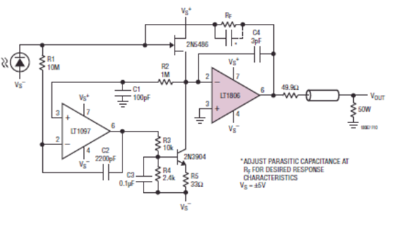
Given this amplifier circuit in the diagram above for a photodiode from LinearTechnologies, With resistor value RF varied from 100kOhms to 1MOhms, total output noise was below 1mV (RMS) measured over a 10MHz bandwidth.

The -3dB Bandwidth is 4.6MHz (RF =200kOhm); As a result, we can use a 1MHz or 2MHz modulation frequencies for the background cancelation.

MY QUESTION:
1. Why was a 1MHz or 2MHz chosen as modulation frequency for background cancellation? and why do we need background cancellation?
2. What is the importance of knowing the total output noise?
3. What is meant by 10MHz bandwidth? and why was this band of frequency chosen?

I'm ashamed2 ask because the question may look lame to experienced people, but i dont know it and will greatly appreciate your answer.

Abel
 

Hi my friend
It is simple , because , the filtering of a 1MHZ is very simple ( because it is an RF wave at MW range ).
Best Wishes
Goldsmith
 

MY QUESTION:
1. Why was a 1MHz or 2MHz chosen as modulation frequency for background cancellation? and why do we need background cancellation?
2. What is the importance of knowing the total output noise?
3. What is meant by 10MHz bandwidth? and why was this band of frequency chosen?

I'm ashamed2 ask because the question may look lame to experienced people, but i dont know it and will greatly appreciate your answer.

Abel
Without some info on the application or the document that design comes from, it's hard to answer precisely...

1. I assume this is for data transmission, so modulating the signal to a carrier frequency at which there is little ambient interference is a good idea. It probably doesn't have to be a specific frequency, just one with low ambient noise. But the term background cancellation is strange... it doesn't cancel the background per se.
2. So that you can get an idea of what sort of noise is introduced by the circuitry. May be important for evaluating the overall noise figure of a channel.
3. If you say an amplifier has a certain bandwidth, say 4.6MHz, then that means that the gain of the amplifier is flat across a span of 4.6MHz (in this case the amplifier operates at baseband, so it spans from 0Hz to 4.6MHz). For the 10MHz noise measurement, that means that their measurement of the noise is only for that band of frequencies. The bandwidth of a noise measurement will directly affect the overall power of the noise, so it's important to specify what bandwidth is used when reporting noise measurements. They probably chose 10MHz just because it covers the full bandwidth of the amplifier.
 
  • Like
Reactions: aakeni

    aakeni

    Points: 2
    Helpful Answer Positive Rating
Without some info on the application or the document that design comes from, it's hard to answer precisely...

1. I assume this is for data transmission, so modulating the signal to a carrier frequency at which there is little ambient interference is a good idea. It probably doesn't have to be a specific frequency, just one with low ambient noise. But the term background cancellation is strange... it doesn't cancel the background per se.
2. So that you can get an idea of what sort of noise is introduced by the circuitry. May be important for evaluating the overall noise figure of a channel.
3. If you say an amplifier has a certain bandwidth, say 4.6MHz, then that means that the gain of the amplifier is flat across a span of 4.6MHz (in this case the amplifier operates at baseband, so it spans from 0Hz to 4.6MHz). For the 10MHz noise measurement, that means that their measurement of the noise is only for that band of frequencies. The bandwidth of a noise measurement will directly affect the overall power of the noise, so it's important to specify what bandwidth is used when reporting noise measurements. They probably chose 10MHz just because it covers the full bandwidth of the amplifier.

hi,

thankx a lot for your response...I'm honestly relieved that some one responded at all.

here's more information to help clarify my first two questions,

my questions arose from statements made in a presentation for a design work to determine what Analog to digital converter (ADC); 8bit, 12 bit etc; will be suitable to measure output signal from a photodiode. The photodiode is SIEMENS/INFINEON SFH213FA. The circuit design was obtained from LightTechnologies.

The presentation continues by stating that since the "maximum output voltage from the photodiode is 5V and the total output noise was below 1mV [RMS], thus the signal to noise ratio is 5,000 (5V divided by 1mV), and since a 12 bit ADC has a resolution of 2^12 = 4096 bits, it is possible to measure the output signal from the photodiode." The presentation also notes that the total output noise of 1mV[RMS] was obtained when the the value of the feedback resistor was varied from 100KOhms to 1MOhms.

*****New Question******
How does one determine the right ADC to use for a particular signal to noise ratio? is there a formula?
*************************

*****MY OLD QUESTION- correction*****

1. What if the term in my question 1 becomes "background noise cancellation", assuming the writer mistakenly ommitted the word 'noise' ? what will your answer to my question1 be? I'd appreciat if you relate your answer it to the statement in the question where the -3dB bandwidth for the amplifier was mentioned ..."Since the -3dB bandwidth is 4.6MHz, we can use a 1MHz or 2MHz modulation frequency for background 'noise' cancellation?". How does one determin the right modulation frequency to use? is there a formula?


If you can, please simplify your answer as much as you can; i'm new to the world of electronics and rilly want to understand this.

Thanks once again.
 

The circuit design was obtained from LightTechnologies[/B].
Are you sure you don't mean Linear Technology? I recognize their schematic diagrams anywhere.... could you link the document?

The presentation continues by stating that since the "maximum output voltage from the photodiode is 5V and the total output noise was below 1mV [RMS], thus the signal to noise ratio is 5,000 (5V divided by 1mV), and since a 12 bit ADC has a resolution of 2^12 = 4096 bits, it is possible to measure the output signal from the photodiode." The presentation also notes that the total output noise of 1mV[RMS] was obtained when the the value of the feedback resistor was varied from 100KOhms to 1MOhms.

*****New Question******
How does one determine the right ADC to use for a particular signal to noise ratio? is there a formula?
*************************
There are a few ways to choose an ADC. First of all, the method described above is pretty crude, and may not give best results. Generally what you want out of your ADC (aside from obviously being fast enough to sample your signal) is a good enough dynamic range to measure your signal without degrading its SNR or THD. An ADC never has as much dynamic range as its resolution implies. Rather than explain everything myself (which would be tedious) I'll just direct you to look up the following terms:
SINAD - Wikipedia, the free encyclopedia
Effective number of bits - Wikipedia, the free encyclopedia
Total harmonic distortion - Wikipedia, the free encyclopedia
Spurious-free dynamic range - Wikipedia, the free encyclopedia
These are all interrelated terms which will degrade the effective performance of an ADC. Any good manufacturer will supply these characteristics under various test conditions, allowing for you to decide if they suit your needs.

When I choose an ADC, I generally do so based on its SFDR. The signal has its own SFDR before conversion, and ideally the SFDR of the ADC is better, so it doesn't impact the measurement severely. Some people will use SINAD instead, but that generally requires a significantly better ADC, and the actual benefit may not be as great.

1. What if the term in my question 1 becomes "background noise cancellation", assuming the writer mistakenly ommitted the word 'noise' ? what will your answer to my question1 be? I'd appreciat if you relate your answer it to the statement in the question where the -3dB bandwidth for the amplifier was mentioned ..."Since the -3dB bandwidth is 4.6MHz, we can use a 1MHz or 2MHz modulation frequency for background 'noise' cancellation?". How does one determin the right modulation frequency to use? is there a formula?
This would be a whole lot easier if you linked the actual document...
Actually my problem isn't with the term "noise" so much as it is with "cancellation." As I said before, but shifting your signal (you still haven't specified what your signal being modulation is) into a frequency band where there is little ambient signal/noise, you can preserve the SNR of your signal during transmission. This isn't "cancellation," you're just avoiding interference by frequency shifting.

As for the relation between bandwidth and modulation frequency to use, the only thing tying them together is that the modulation frequency has to be within the bandwidth of the amplifier. Theoretically, anything 4.6MHz or lower would work. Why they specifically chose 1 or 2MHz, I can't say for sure.
 

Status
Not open for further replies.

Similar threads

Part and Inventory Search

Welcome to EDABoard.com

Sponsor

Back
Top