Continue to Site

Welcome to EDAboard.com

Welcome to our site! EDAboard.com is an international Electronics Discussion Forum focused on EDA software, circuits, schematics, books, theory, papers, asic, pld, 8051, DSP, Network, RF, Analog Design, PCB, Service Manuals... and a whole lot more! To participate you need to register. Registration is free. Click here to register now.

variable 40v dc current limiter

Status
Not open for further replies.

Cecemel

Member level 5
Joined
Apr 16, 2014
Messages
89
Helped
0
Reputation
0
Reaction score
0
Trophy points
1,286
Location
Belgium
Activity points
2,043
hey!
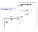
i 've build a variable dc power supply (0-40v) for testing but i wanna be able to limit the current. Can someone give me a simple circuit (i 'am a beginner, even circuits with ground are confusing for me:wink:) and some explanation plz?
Regards Cecemel!:)
 

a very simple solution to limit direct current is a resistor in series........

R=(v(input)-V(output))/I(output)
 

If you want an extremely simple current limiter, where efficiency is not a concern, use a power BJT in the open collector mode with a limited base current. The limit of the base current will determine the limit of the output current. The current will be limited to gain*base_current. (Typical gain of power BJTs is between 4 to 8) Use a large heat-sink with the BJT.
See attachment below.
 

Attachments

  • Eda.JPG
    Eda.JPG
    22.8 KB · Views: 109

Here you go:
image.jpg
(But plz keep in mind that it has to be a variable current limiter)
Ps: is it right that the potmeter has to be connected at the blue points and that it has to be 4k ohm?

Pps:wink:: is it right that the ground points (red) have to be connected to each other (don't have a metal case)
 
Last edited:

Yes, all the red points are joined together. The potentiometer between the blue points will adjust the output voltage but not the current. I would suggest the best solution is to wire a current limiting stage between C1 and C5, this will still allow you to set the voltage using the potentiometer and allow it to stay regulated up to the point where the limiter kicks in.

What kind of limiter do you want? There are several types. Do you want the voltage to gradually fall as the current exceeds the limit (constant current mode) or do you want it to shut down completely when overloaded so you have to manually reset it?

Brian.

At 40 V i'am gonna have a much lower current than at 1 v. Right?
So I want to have the same current (lower at 40 v, higher at 1 v)
but whenever i turn down the potmeter (from the current limiter, not from the voltage) i want (at whatever voltage i am)the current to (if possible linear) drop to (almost) nothing.
Thanks Cecemel
 

If you want an extremely simple current limiter, where efficiency is not a concern, use a power BJT in the open collector mode with a limited base current. The limit of the base current will determine the limit of the output current. The current will be limited to gain*base_current. (Typical gain of power BJTs is between 4 to 8) Use a large heat-sink with the BJT.
See attachment below.

Thanks,
But can you give some more explanation about the circuit?
Get ready to be flooded with noob questions;-):
(Where is the input, minimum amp it delivers when potmeter is turned to min, power consuming, do i have to connect the output of my power supply to the input of this circuit, what is v1, what type of transistor is q1)

- - - Updated - - -

a very simple solution to limit direct current is a resistor in series........

R=(v(input)-V(output))/I(output)

You mean like this?:
image.jpg
 

Do as Frank suggests and wire your VOLTAGE setting potentiometer instead of the lower two resistors on the right.

I think you are confusing constant voltage, constant current and constant power. Consider what current and 'ideal' power supply would deliver into a short crcuit, would it make any difference what the voltage was set to? However, it sounds like what you are asking for is a constant voltage supply that changes to constant current when overload point is reached, this is the way most PSUs work.

Brian.
 

Status
Not open for further replies.

Similar threads

Part and Inventory Search

Welcome to EDABoard.com

Sponsor

Back
Top