Vermes
Advanced Member level 4
It is a power board which can be used to power a universal lathe. The assumption of this design was to activate again an old lathe, using popular and easily available components.
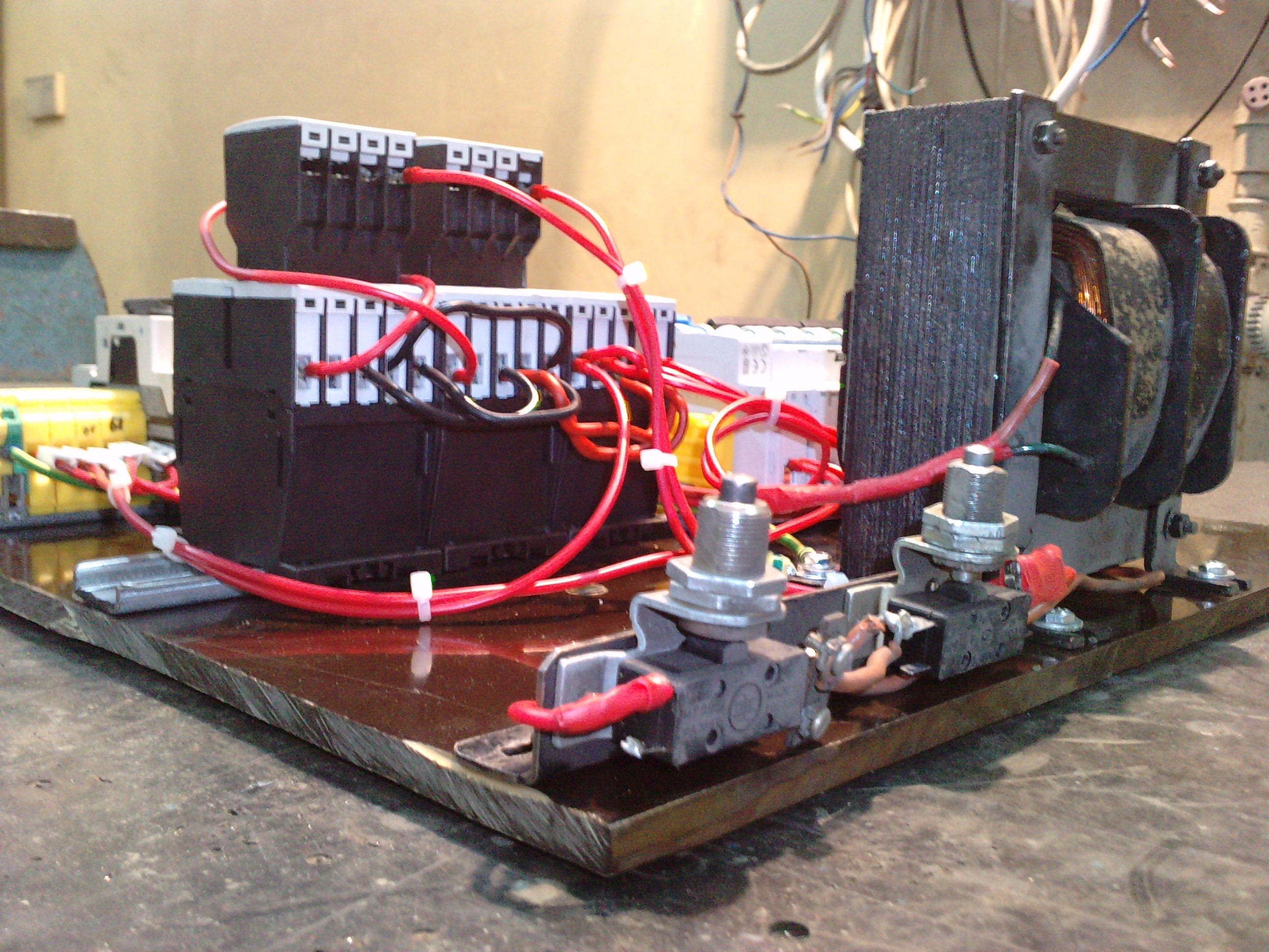
The board which was mounted on the table, can be removed. The whole device was made on 10 mm thick Bakelite board with components screwed to it by M5 screws.
The lathe is powered from alternating voltage with line-to-line voltage 400V and 50Hz frequency through a 4x4mm2 cable from TN-C, while the lathe is made on the variant TN-S, so on the board there is a point PEN, to which the housing of the device and stave connected to ground are attached. The lathe is equipped with three-phase motor with P=3kW.
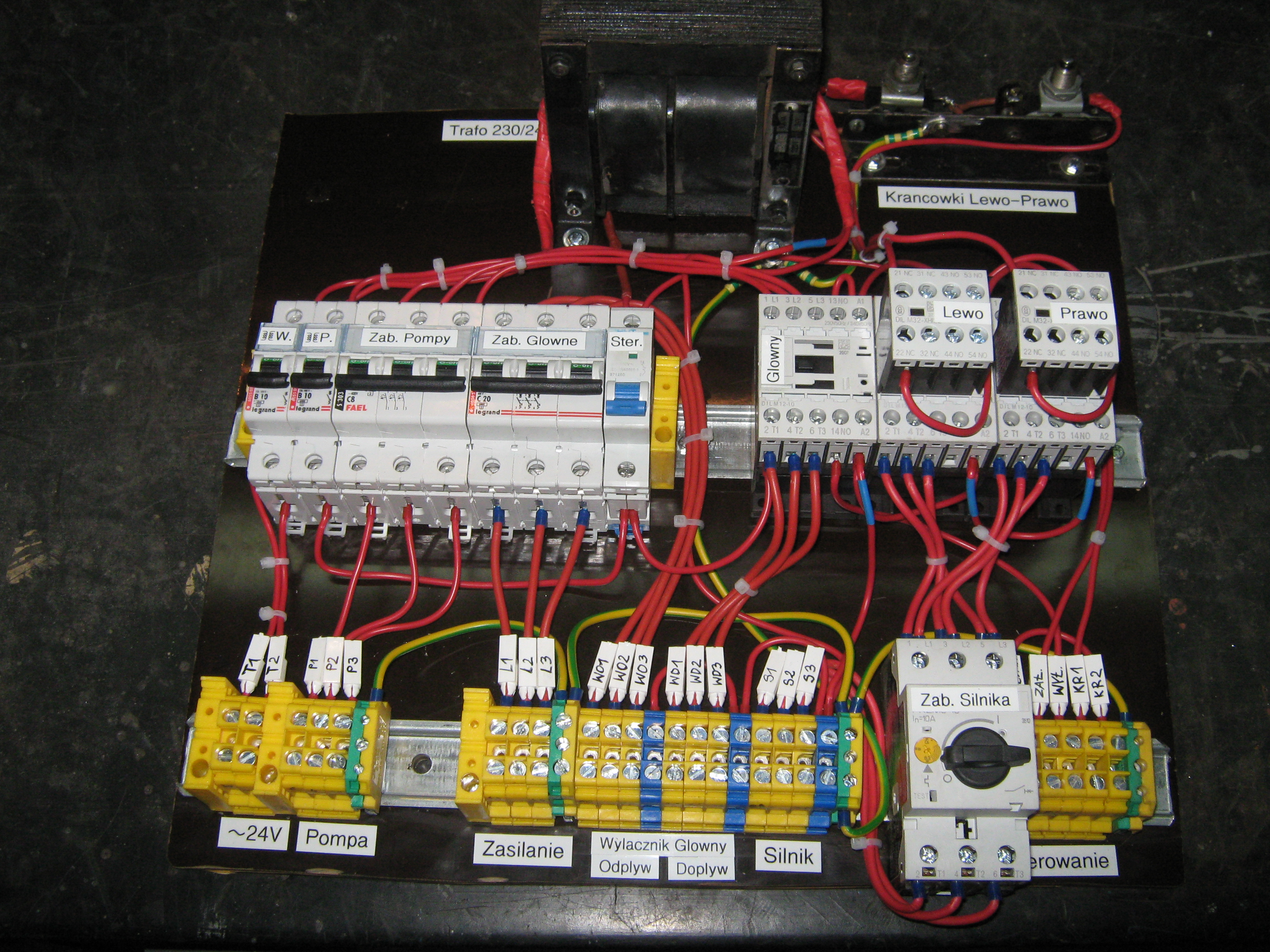
Elements of the board:
- safety transformer ~100VA 230/25V
- base with directional limit switches (contact closures)
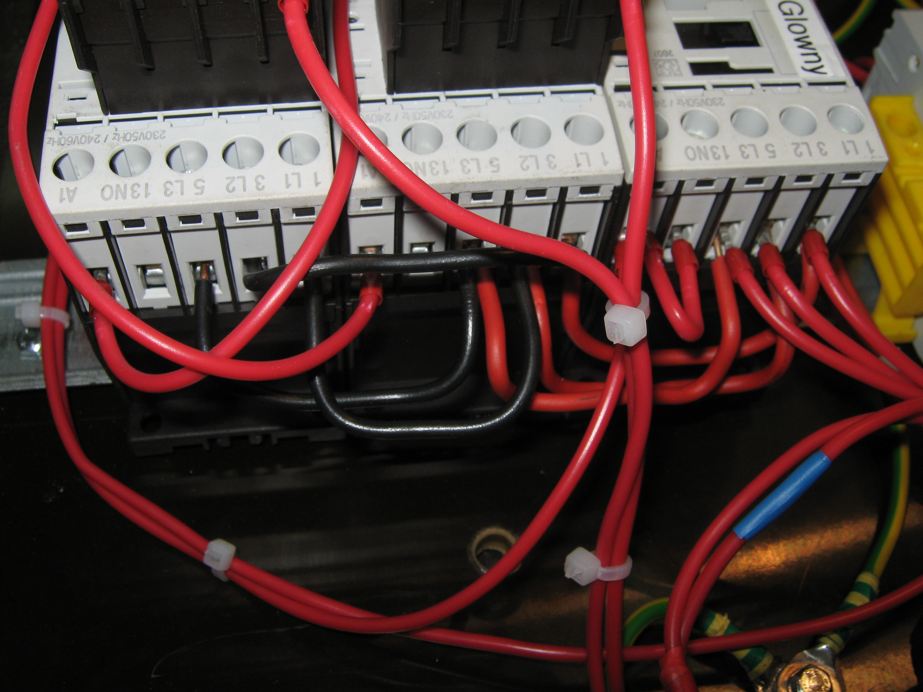
- three DIL M(C)12 contactors – additional auxiliary contacts were applied in two of them
- motor switch PKZM04
- three-phase overcurrent protection type “s” C20
- three-phase overcurrent protection type “s” C8
- two one-phase overcurrent protections type “s” B10
- one-phase overcurrent protection type “s” B6
- joining strip with connections ZUG 10mm2
It is recommended to make connections using a cable, the best in different colors, or mark it appropriately. It is important to ensure that protection clamp ZUG are of type PE (connected electrically with the assembly stripe).
In this case, 2,5mm2 cable was used with rated voltage of 500V for high current connections and 1,5mm2 cable 500V for control circuits.
After switching the external supply, voltage appears on the C20 protection, from where the circuit through the main switch ŁUK25A passes to the main contactor DIL M(C)12. The contactor is controlled from the control cassette on the lathe panel, and is equipped with buttons: on, off and emergency.
Then the high current circuit directs towards the contactors of rotation direction change, then to PKZM switch and then directly to the board to the lathe motor connection.
Control voltage is taken from the main switch through “s” B6 switch, NO limit switch of the rotating element cover, emergency stop to the control keys. Left-Right contactors control is protected against the simultaneous activation of both contactors through auxiliary contacts of these contactors.
Pictures:

Schematic:

Link to original thread (useful attachment) - Tablica zasilająca tokarki uniwersalnej TU