Vermes
Advanced Member level 4

- Joined
- Aug 2, 2011
- Messages
- 1,163
- Helped
- 0
- Reputation
- 0
- Reaction score
- 0
- Trophy points
- 1,316
- Activity points
- 22,318

It is a design of universal converter USB-MIDI. Firmware can be taken from uCapps.de (it was created to cooperate with first versions of MIDIBox. The module was based on microcontroller PIC18F4550 and allows for additional connection with four MIDI-I2C converters, also from MIDIBox project.
What is the main advantage of this project? Unlike cheap converters available on the market, it provides good quality. Delays in typical applications are usually 0,5 second or even more, regardless of the configuration. There is also a possibility to expand the device by additional outputs.
One of the assumptions was to create the smallest possible board with the possibility to connect four modules MIDI-I2C when it is needed. The board was to be one-sided, with through hole assembly.
PCB:
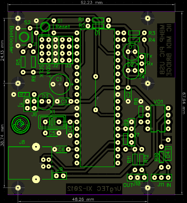
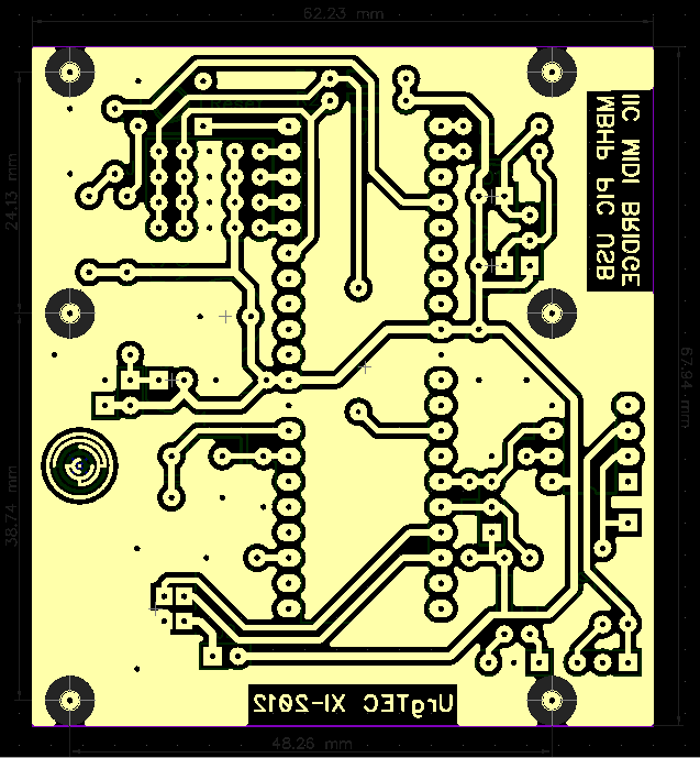
As you can see, the PCB is really small (62x68mm). There are many theoretically unnecessary components such as connector J5 for connecting an external power supply 5V and jumper J9 for disconnecting the supply through USB port. Moreover, all the LEDs have their own connectors for connecting them on cables if you want. Of course, you can solder cables instead LEDs, but perhaps you will need a double set for indication of work. Joints J1-J3 are used for connecting maximum of four modules MIDI-I2C. Not used pins of the microcontroller have to be connected to Vdd. Joint J7 allows for connecting the module to the main board of the MIDIBox in version on the PIC. In this case you must not mount the optocoupler in this module, nor in MIDIBox.
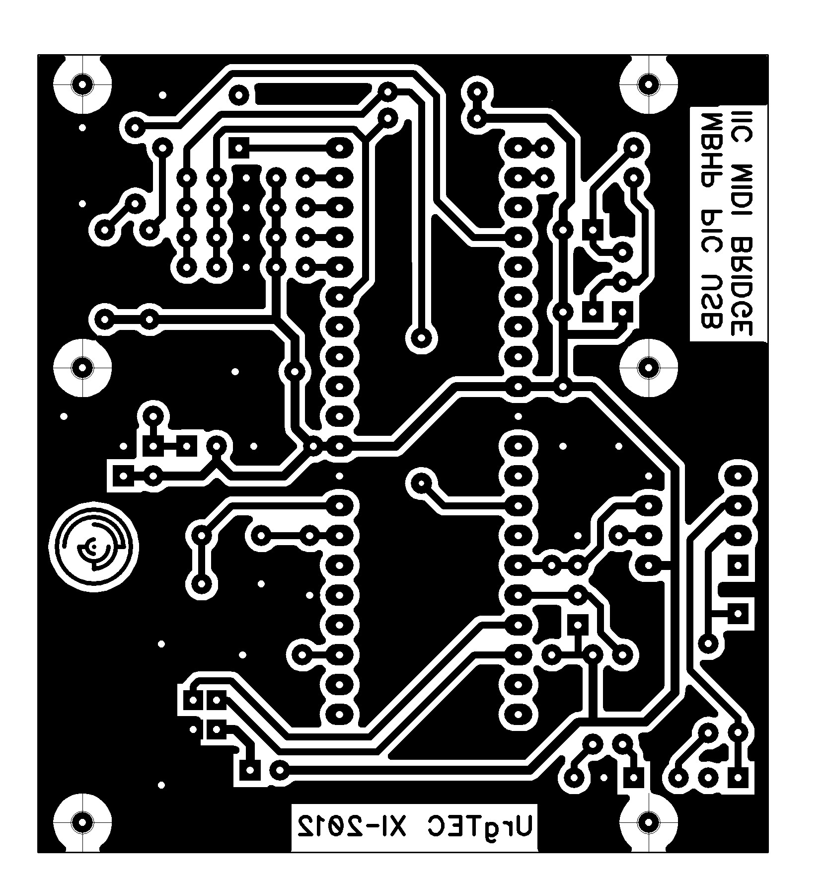
PCB for thermal transfer in resolution of 600DPI:
Prototype:
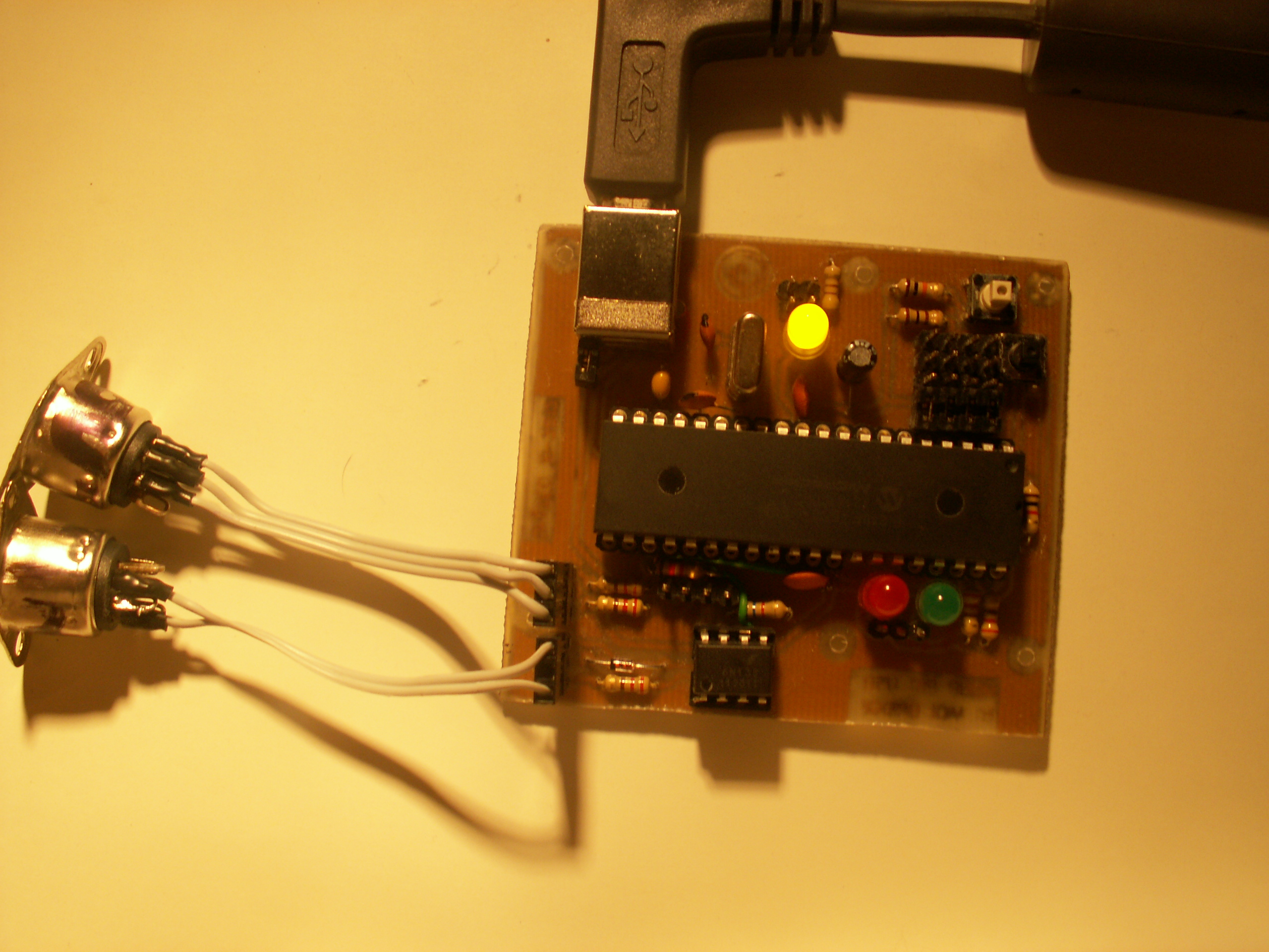
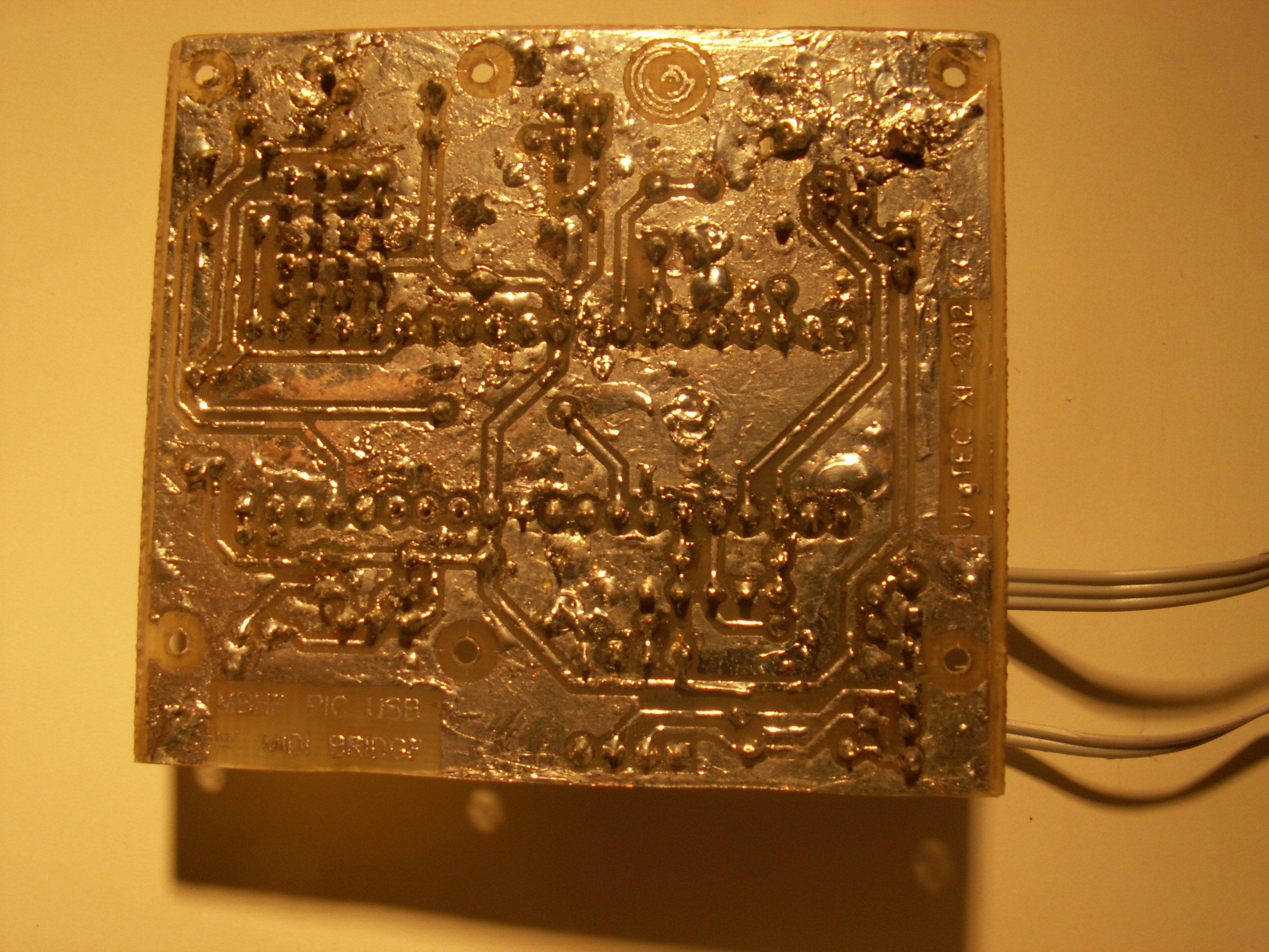
The board is slightly different from these pictures (especially near the optocoupler) due to the fact that it was incorrectly designed. It was necessary to solder two cables, cut two paths and a small jumper. All the holes were made using 0,6mm drill, and then some of them were enlarged using 1mm drill. Mounting holes were made using the 2mm drill for metal.
In the end, note that the Bootloader created by Microchip does not cooperate with Windows7 because of the old type drivers, which can not be installed (although this problem may be solved using the Microchip tools set – available in the attachment to the original thread). This is why it is important to upload the right firmware.
Attachment to the original thread contains: driver, program for Bootloader support, examples of using USB interface, newer version of Bootloader's code.
Useful links:
**broken link removed**
**broken link removed**
Link to original thread (useful attachment) - (MIDIBox Hardware Platform) Uniwersalny konwerter USB-MIDI