Continue to Site
Follow along with the video below to see how to install our site as a web app on your home screen.
Note: This feature may not be available in some browsers.
#pragma config OSC=INTIO67, LVP=OFF, MCLRE=ON , WDT=OFF
Is the "Configuration Bits set in code" check box checked?
BigDog
#include <p18f4620.h>
#include <usart.h>
#include <delays.h>


// INTIO67 configures internal oscillator
//#pragma config OSC=INTIO67, LVP=OFF, MCLRE=ON , WDT=OFF

void setup(void)
{
	/* Clock Setup*/
	OSCCON = 0b01110010; //select 8 MHz clock

	/* Port Set Up*/
	ADCON1 = 0b00001111; //set all pins to digital mode
	TRISD = 0x00;
	TRISA = 0x00;
	TRISB = 0b00000000;
	TRISC = 0b10000000; // RX is an input, TX is output


	/* Interrupt Setup */
	INTCON = 0x00; /* Clear Registers */
	PIR1 = 0x00;
	PIE1 = 0x00;


  // Turn on the 4 LEDs
 // Microchip recommends writing to the PORT Latch rather than the PORT Pins
	LATBbits.LATB0=1;
	LATBbits.LATB1=1;
	LATBbits.LATB2=1;
	LATBbits.LATB3=1;


}


void main(void)
{
    int n = 12;

	setup();

  while(1)
  {
	while (n--)
	{

		Delay10KTCYx(100);

                // Blink the 4 LEDs
               // Microchip recommends writing to the PORT Latch rather than the PORT Pins
	       LATBbits.LATB0 = ~LATBbits.LATB0;
	       LATBbits.LATB1 = ~LATBbits.LATB1;
	       LATBbits.LATB2 = ~LATBbits.LATB2;
	       LATBbits.LATB3 = ~LATBbits.LATB3;


	}

   OpenUSART (USART_TX_INT_OFF & USART_RX_INT_OFF & USART_ASYNCH_MODE & USART_EIGHT_BIT & USART_CONT_RX & USART_BRGH_LOW, 12);

   n = 150;

	while (n--)
	{

		Delay10KTCYx(100);

        putrsUSART(" Hello World! ");


	}

    CloseUSART();
  }

}However, if you open the project up and then program the PIC, neither work.
BigDog
You mean without opening MPLAB, the file I sent you worked but when you programmed through MPLAB it didn't?
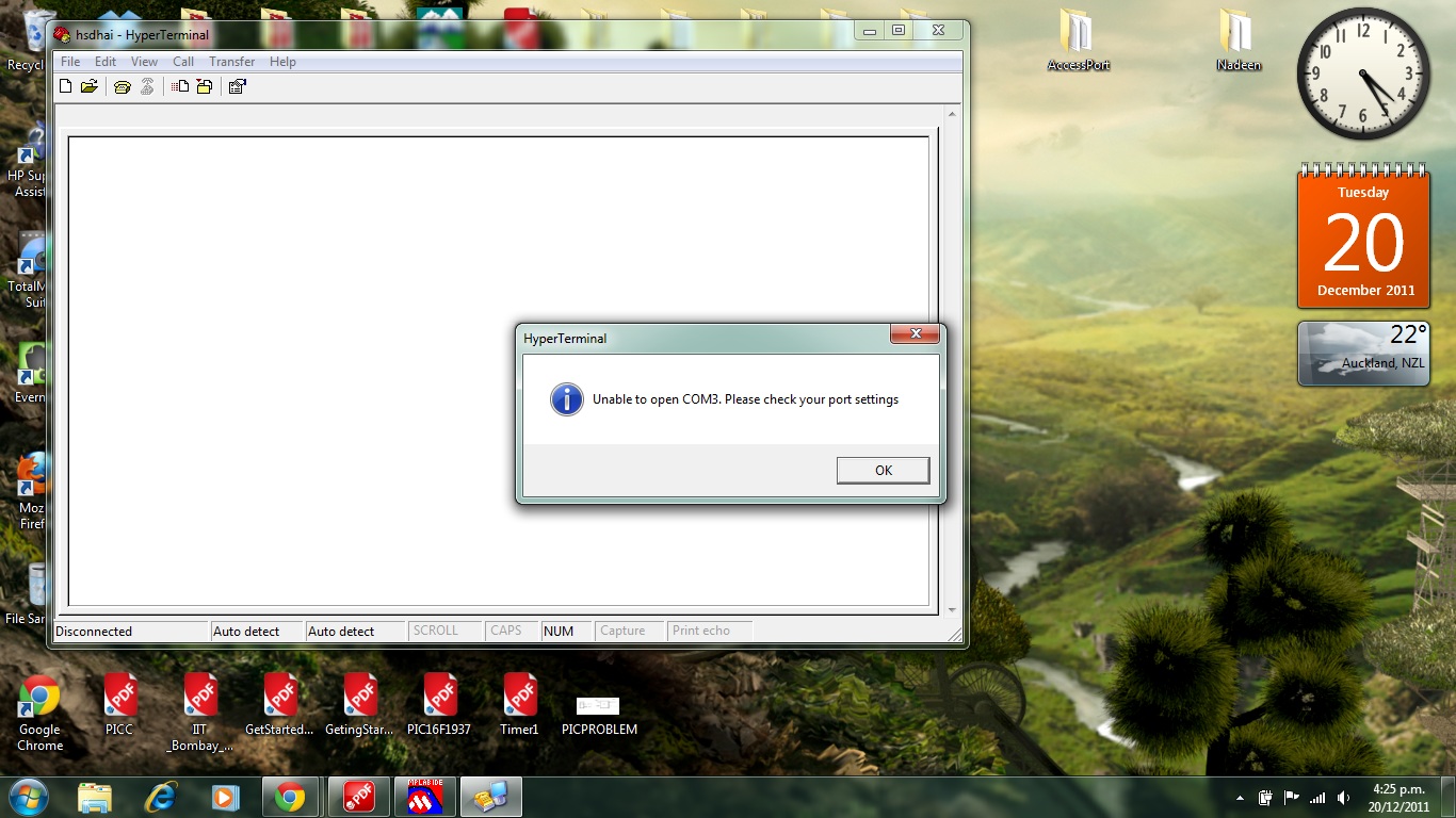
This morning I got a new PIC18f4620 and installed in my board, Same error ! I think I will switch to a PIC16 and HIGH-TEC C now !
Ok so I have some new info to share on this issue. I went back to perform a loop back test on the board. I took the PIC out and connected Tx and Rx on the DIP and as expected it worked fine!
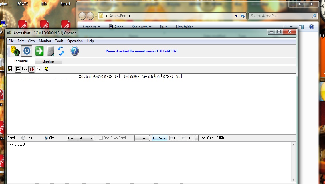
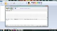
Test1: Nothing connected to Tx and Rx. I used AccessPort to send "This is test" to the board, but since the two pins ( Tx and Rx) arents connected, we shouldnt get anything back right? But to my surprise I got this( see image below). Is this just noise or what exactly is it? Btw test result is not repetitive- sort of like one off!
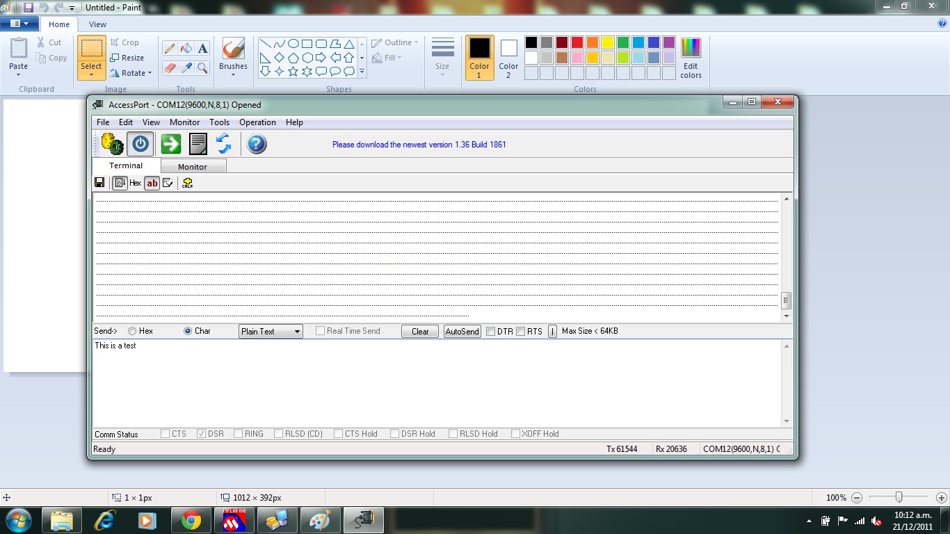
Test 2: I connected wire to Tx and left thr other end open. I got this ( see pic below) . Is that just noise? This test result is repetitive! Also when I "stop send" , the lines still keeps going. Its constantly sending these "dots" to PC !
This morning I got a new PIC18f4620 and installed in my board, Same error ! I think I will switch to a PIC16 and HIGH-TEC C now !
Ok so I have some new info to share on this issue. I went back to perform a loop back test on the board. I took the PIC out and connected Tx and Rx on the DIP and as expected it worked fine!
Test1: Nothing connected to Tx and Rx. I used AccessPort to send "This is test" to the board, but since the two pins ( Tx and Rx) arents connected, we shouldnt get anything back right? But to my surprise I got this( see image below). Is this just noise or what exactly is it? Btw test result is not repetitive- sort of like one off!
Test 2: I connected wire to Tx and left thr other end open. I got this ( see pic below) . Is that just noise? This test result is repetitive! Also when I "stop send" , the lines still keeps going. Its constantly sending these "dots" to PC !
#include <p18f4620.h>
#include <stdio.h>
#include <delays.h>
#include <usart.h>

// INTIO67 configures internal oscillator
#pragma config OSC=INTIO67, LVP=OFF, MCLRE=ON , WDT=OFF

void setup(void)
{
	/* Clock Setup*/
	OSCCON = 0b01110010; //select 8 MHz clock

	/* Port Set Up*/
	ADCON1 = 0b00001111; //set all pins to digital mode
	TRISD = 0x00;
	TRISA = 0x00;
	TRISB = 0b00000000;
	TRISC = 0b10000000; // RX is an input, TX is output


 // Turn on the 4 LEDs
 // Microchip recommends writing to the PORT Latch rather than the PORT Pins
	LATBbits.LATB0=1;
	LATBbits.LATB1=1;
	LATBbits.LATB2=1;
	LATBbits.LATB3=1;


	/* Interrupt Setup */
	INTCON = 0x00; /* Clear Registers */
	PIR1 = 0x00;
	PIE1 = 0x00;
	TMR1L = 0x00;
	TMR1H = 0x00;
	T1CON = 0x00;
	RCON = 0x00;


    /* RS232 Enable */
	// OpenUSART Configures The Next Three Lines
	//RCSTA = 0b10000000;
	//TXSTA = 0b00100000;
	//BAUDCON = 0b01000000;

	// USART 9600 8-N-1
	OpenUSART (USART_TX_INT_OFF & USART_RX_INT_OFF & USART_ASYNCH_MODE & USART_EIGHT_BIT & USART_CONT_RX & USART_BRGH_LOW, 12);

}


#pragma code
void main(void)
{
	setup();

	while (1)
	{

		putrsUSART(" Hello World! ");
		//while(BusyUSART());
		Delay10KTCYx(100);

	}
}