Continue to Site

Welcome to EDAboard.com

Welcome to our site! EDAboard.com is an international Electronics Discussion Forum focused on EDA software, circuits, schematics, books, theory, papers, asic, pld, 8051, DSP, Network, RF, Analog Design, PCB, Service Manuals... and a whole lot more! To participate you need to register. Registration is free. Click here to register now.

Understanding SRAM current consumption-71V35761S166PFGI

Bjtpower

Full Member level 5
Full Member level 5
Joined
Dec 24, 2015
Messages
297
Helped
2
Reputation
4
Reaction score
2
Trophy points
1,298
Activity points
3,893
Hi,

I have SRAM 71V35761S166PFGI in my circuit and i wanted to check worst case current consumption for the same IC.
i have passed through datasheet and i am confused getting exact max current required for the SRMA IC.

SRAM is interfaced with Microcontroller
 
Has to be interpolated using "DC Electrical Characteristics", using clock frequency and enable duty cycle information from your application. As stated, the current values are maximum guaranteed values, actual or "typical" current consumption will be probably lower.

1704454061463.png
 
Has to be interpolated using "DC Electrical Characteristics", using clock frequency and enable duty cycle information from your application. As stated, the current values are maximum guaranteed values, actual or "typical" current consumption will be probably lower.

View attachment 187555
How to get typical current consumption? Assumed Clk frequency: 200MHZ, Duty cycle: 0.5
 
Hi,

according the datasheet it shows 360mA at 200MHz and 320mA at 166MHz.
Thus the dynamic consumption is 40mA/36MHz or 235mA at 200MHz.

The static current is 360mA - 235mA = 125mA. at 50% duty cycle it´s about 65mA.

The other 50% is standby current of 30mA. --> 15mA

So total 315mA.
But there will be additional current due to pin capacitance of 7pF each IO. It surely depends on code - which we don´t know. I = 0.5 * C * V * V * f
And there is the RAM_independent trace capacitance and pin capacitance of connected ICs. We don´t know.

Klaus
Hi,

I am sorry but i did not understand How you calculated or interpreted dynamic current consumption?
If you dont mind, can you please explain step by step to understand clearly.
 
"At f = f MAX, inputs are cycling at the maximum frequency of read cycles of 1/t CYC while ADSC = LOW;
f=0 means no input lines are changing."

If 200MHZ, Duty cycle: 0.5
IDD= 360 mA * 50% = 180 mA
ISB1= 30 mA * 50% = 15 mA
Average Load = (180 + 15)/2 mA = 97.5 mA max over entire commercial temperature range.

Since dynamic current is due to time spent between thresholds VL and VH,
and FETS run slower when hot. This is guaranteed to be the limit which occurs at the maximum commercial temperature only, worst case, but typically less.

Industrial temp range is not offered at 200 MHz.

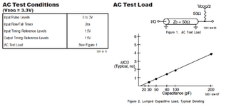
The load for the above tests was given as follows at Vddq= 3.3 V where 50 Ohms is the trace impedance and also terminated by 50 at 1.67V
1704711850128.png


Current will be slightly higher at 3.3V + 5% as RdsOn is slightly lower driving load capacitance BUT will be 2x as much dynamic current if the lumped load capacitance is 200 pF for a rise time of 4 ns. (since Ic= C dV/dt, but C is nonlinear, so dt is more accurate between VL and VH.)
 

Attachments

  • 1704712019013.png
    1704712019013.png
    112 KB · Views: 66
Last edited:
Hi
Hi,

I am sorry but i did not understand How you calculated or interpreted dynamic current consumption?
If you dont mind, can you please explain step by step to understand clearly.
It´s pretty basic math.
and already given in post#6.
* 200MHz -166MHz = 34MHz (My bad: I had a typo and wrote 36MHz)
* 360mA - 320mA = 40mA
* divide both to get 1.176 mA/MHz


So let´s do it using excel:
chart.png


You see it´s just writng the two current values for the two frequency values into the chart.
Then make Excel draw a graph.
Then say "add trend line"
Then say "add formula"
it says Y (mA) = 1.1765x (MHz) + 124.71.
So on 0 MHz ... you get the 124.71mA ... about 125mA of static current. 0 MHz = no duty, no activity.
And you get 1.1765 mA per MHz of dynamic (activity dependent) current.
so at 200MHz you get 235.3mA of dynamic (caused by activity) current.

Klaus
 
Hi

It´s pretty basic math.
and already given in post#6.
* 200MHz -166MHz = 34MHz (My bad: I had a typo and wrote 36MHz)
* 360mA - 320mA = 40mA
* divide both to get 1.176 mA/MHz


Klaus
But you didn't answer the question correctly

If 200MHz, Duty cycle: 0.5
IDD= 360 mA * 50% = 180 mA
ISB1= 30 mA * 50% = 15 mA
Average Load = (180 + 15)/2 mA = 97.5 mA max over entire commercial temperature range which means at 70'C @ Vdd=3.3V
1704751357700.png
 
If 200MHz, Duty cycle: 0.5
IDD= 360 mA * 50% = 180 mA
ISB1= 30 mA * 50% = 15 mA
Average Load = (180 + 15)/2 mA = 97.5 mA max over entire commercial temperature range which means at 70'C @ Vdd=3.3V
I see your point.
In your case it´s like (example) 10ms @ 200MHz and 10ms idle. (i.e. 200MHz bursts for 50% of the time)

My idea was different:
200MHz continously, but 2.5ns active each and 2.5ns idle each.
Thus my result was different.

Now that I think about it, your idea maybe makes more sense.
Still I don´t think your math is correct either. You use 50% on each value ... thus it already takes care about the "average". No need to divde it again by 2.

I guess we need the OP to tell us how he wants it to operate.

Klaus
Right but I should average the power to compute average load for energy consumption regardless if it is 2 cycles or 2 days. 97.5 mA

Max power is 200 mA with 100 pF || 50 Ohms to Vdd/2 load and Vdd= 3.3V @ 70 'C
("active load" may be 100 ohms to Vdd and 100 to Vss This improves bus timing margin at full speed.) There are other speed tricks.
 
Last edited:

LaTeX Commands Quick-Menu:

Similar threads

Part and Inventory Search

Welcome to EDABoard.com

Sponsor

Back
Top