Continue to Site

Welcome to EDAboard.com

Welcome to our site! EDAboard.com is an international Electronics Discussion Forum focused on EDA software, circuits, schematics, books, theory, papers, asic, pld, 8051, DSP, Network, RF, Analog Design, PCB, Service Manuals... and a whole lot more! To participate you need to register. Registration is free. Click here to register now.

Understand this simple circuit

Status
Not open for further replies.

angy

Full Member level 3
Joined
Jul 9, 2008
Messages
151
Helped
5
Reputation
10
Reaction score
5
Trophy points
1,298
Activity points
2,341
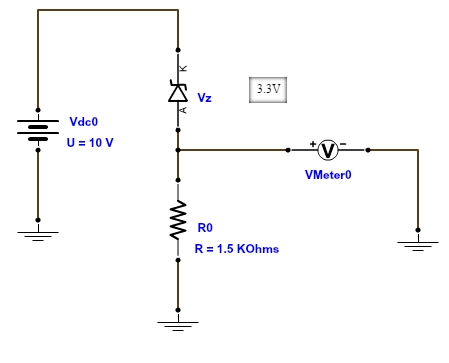
I was troubleshooting a circuit and i came to this part of circuit .it contains zener diode(3.3V) and a pull down resistor.When i apply supply voltage(10V) i should get 6.7 V.But during troubleshooting i found full 10V across output .later i found resistor was not properly grounded .Now my doubt is when one end of resistor is not grounded how do we get 10V across output.
1313015700_1421562998.png
 

I think your reading was because of leakage current
 

Now my doubt is when one end of resistor is not grounded how do we get 10V across output.
1313015700_1421562998.png

If your resistor is not grounded, that mean you have an open circuit, thus no current flow. Therefore you will see the entire full ten voltage at the output.

If that is confusing, just imagine the open circuit as an infinitely large resistor. Now apply the basic voltage divider rule, of course the entire 10V will drop across this infinitely large resistor.
 
  • Like
Reactions: angy

    angy

    Points: 2
    Helpful Answer Positive Rating
If the voltmeter has a typical high resistance than the current through the Zener diode is very small.
This current is likely less than the diode leakage current so basically the full voltage appears across the voltmeter.
 

Status
Not open for further replies.

Similar threads

Part and Inventory Search

Welcome to EDABoard.com

Sponsor

Back
Top