Gaber Mohamed Boraey
Full Member level 2
Hello everyone , hope you all fine and in a good health
I am willing to do this circuit for capacitors test, as I’m into electronics repair and measuring capacitor with meter, “ measuring only capacitance “ not enough for me, that’s why I’m thinking build this circuit
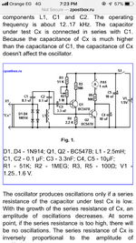
I’ve read about and know that it’s colpitts oscillator, what I Don’t understand is the q2 purpose, blog author say it’s for rectifying, which i don’t understand , can you clarify for me?
Here is the blog
Attached the circuit
Thanks
I am willing to do this circuit for capacitors test, as I’m into electronics repair and measuring capacitor with meter, “ measuring only capacitance “ not enough for me, that’s why I’m thinking build this circuit
I’ve read about and know that it’s colpitts oscillator, what I Don’t understand is the q2 purpose, blog author say it’s for rectifying, which i don’t understand , can you clarify for me?
Here is the blog
Simple ESR meter circuit diagram
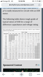
How to build a simple equivalent series resistance meter, its circuit diagram is described in this article
zpostbox.ru
Attached the circuit
Thanks