Continue to Site

Welcome to EDAboard.com

Welcome to our site! EDAboard.com is an international Electronics Discussion Forum focused on EDA software, circuits, schematics, books, theory, papers, asic, pld, 8051, DSP, Network, RF, Analog Design, PCB, Service Manuals... and a whole lot more! To participate you need to register. Registration is free. Click here to register now.

determine the operation point of this simple circuit

Status
Not open for further replies.

akbarza

Full Member level 2
Joined
Dec 18, 2013
Messages
131
Helped
0
Reputation
0
Reaction score
0
Trophy points
1,296
Activity points
2,556
hi
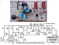
I attached a pic of a circuit and the .asc file( ltspice file).
inthe file MIC is microphon( i did not find symbole or component in ltspice for microphon).
the transistor is pnp. how can i find the Q- point with calculation? then according to bias point,
what is the class of this transistor?
why in this circuit, a pnp transistor has been used and not a npn transistor?
thanks
 

Attachments

  • fm_transmitter1_pic.pdf
    142.7 KB · Views: 138
  • fm_transmitter1.zip
    595 bytes · Views: 107

You need a datasheet of the microphone used in the circuit, apparently an electret microphone.
--- Updated ---

I notice that most electret microphone datasheets have only vague DC operation point specifications. It may be necessary to adjust R1 for a given micropone. I would assume 1 V voltage drop across the microphone as a starting point.
 
Last edited:

HI
i read about lc tank and colpitis and hartley oscillators.
are l1, c2,c3 elements lc tank?
i do not understand why this way lc tank ic connected to circuit?
is it possible to attach a R between collector and ground and the tank is placed between antenna and ground without any connection between this tank and collector of transistor?
can you explain the feedback path? i think the emitter( antenna) is output. ( for oscillation, positive feedback is needed)so how does output feed back to input(base of transistor)?
thanks
 

It's a common base colpitts oscillator, feedback path is from collector to emitter. Connecting the load at the emitter is unusual but can work. 2N3906 won't necessarily work at the intended operation frequency.
 

The circuit you posted is too simple and might not work. It will have radio frequency changing problems.

Most electret mics need at least 1.5V (when its output level might be attenuated -3dB) and operate at only 300uA. Then with 3V - 2V= 1V across the 10k resistor, its current is 100uA and the electret mic and the base current in the transistor is 300uA which is not enough.

My FM transmitter is powered from a 9V battery and the electret mic and preamp transistor are fed from a 5V low-dropout voltage regulator. The electret mic gets about 2V for its spec'd output level. It is capacitor-coupled to a preamp transistor to boost its output level and add pre-emphasis that all FM radio stations use. Without pre-emphasis boosting high audio frequencies, the transmitter feeding an FM radio sounds muffled like an AM radio, because all FM radios have matching de-emphasis.

The preamp feeds an NPN transistor oscillator similar to your PNP one and its emitter feeds an RF power amplifier to isolate the antenna from the oscillator, so that something moving towards or away from the antenna does not change the oscillator frequency.
 

Attachments

  • FM tx mod4 pic and schematic.jpg
    FM tx mod4 pic and schematic.jpg
    196 KB · Views: 115

It's a common base colpitts oscillator, feedback path is from collector to emitter. Connecting the load at the emitter is unusual but can work. 2N3906 won't necessarily work at the intended operation frequency.
hi Fvm
as i think that the microphon signal is input and it is connected to base and out put is taken from emitter, so i think the circuit is common collector .
am i thinking in wrong way?
 

The microphone signal is the modulation of the oscillator. The microphone signal changes the conduction of the oscillator transistor causing AM. Mist FM radios ignore the AM.
The signal at the emitter has no audio, instead it has modulated VHF.

The microphone signal changes the conduction of the transistor which also causes the capacitance of the transistor to change which changes the oscillator frequency, producing FM.
 

as i think that the microphon signal is input and it is connected to base and out put is taken from emitter, so i think the circuit is common collector .
am i thinking in wrong way?
Connection of modulation signal has nothing to do with oscillator topology. Oscillator is common base because the base terminal is shorted by a capacitor to ground.
 

    akbarza

    Points: 2
    Helpful Answer Positive Rating
Status
Not open for further replies.

Similar threads

Part and Inventory Search

Welcome to EDABoard.com

Sponsor

Back
Top