Continue to Site

Welcome to EDAboard.com

Welcome to our site! EDAboard.com is an international Electronics Discussion Forum focused on EDA software, circuits, schematics, books, theory, papers, asic, pld, 8051, DSP, Network, RF, Analog Design, PCB, Service Manuals... and a whole lot more! To participate you need to register. Registration is free. Click here to register now.

Triac to Anti Parallel Thyristor Shift

Status
Not open for further replies.

mail4harish_s

Newbie level 3
Newbie level 3
Joined
Feb 15, 2008
Messages
4
Helped
0
Reputation
0
Reaction score
0
Trophy points
1,281
Visit site
Activity points
1,315
Hi, I am working on a Triac load control using a 4-20mA signal as an input. Have used a TCA785 and the output from Pins 14 & 15 are fed via 2 forward biased diodes and a resistor to MOC 3021. The triac works just fine and I get a decent output regulation on the input 4-20mA variation.

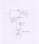
What should I do to my circuit to change the Triac to a antiparallel Thyristor. (I have tried what was given in the 785's datasheet, but that is not suitable for me)

Can anyone suggest minor modifications so that I can remove the triac and put in a thyristor and achieve the same results.
(My power supply is Supply: + 12V and gnd)

Thanks in advance.

S. Harish
 

see the attached picture (size=48KB)
 

Attachments

  • triac_scr.jpg
    triac_scr.jpg
    44.8 KB · Views: 360

Hi Ahsan,
Thank you very much for your pictorial reply. I shall give it a try and write back to you.

- - - Updated - - -

Hi Ahsan,

I just tried working with your design. I had connected a bulb to the anti-parallel scr to test the functioning. It started off well, but in between 120 V to 180 V, the bulb was so very flickering. After 180 V, the output was steady and the final output was 5.2 Volts less than that of input. Please advice on how to proceed from here on.
Friendly
Harish
 

Hi Harish,
The final output is 5.2 volt less. It is normal. It is so because, when you trigger the moc3021 at zero degree to get full output, the SCR does not get triggered instantly. SCR will get triggered when gate current reaches to trigger level. Gate current will start to flow when the sine wave crosses the zero and have some voltage. This voltage divided by 330 ohm+load resistance is the gate current. So SCR will get triggered at some small degree (5 or 10) and hence you are getting 5.2 volt less.
Flickering is strange. It is obvious that flickering is happening near 90 degree. At this angle peak current through moc3021 output is 311/330+load which is less than 1 amp. 1 amp is the maximum allowable output surge current of moc3021.
If the flickering problem is related to surge current limitation, then flickering will be gone if we increase the value of 330 to say 680 ohms or 1k. So check it now.
 

Hi Harish,
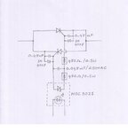
I think there are spikes and noise in the power line. So you need snubber at the output of moc3021. I modified the circuit and shown below.


new_triac_scr.jpg
 

Hi Ahsan, Thanks once again for your replies. I will first try with the 680 Ohms, in order to check for surge current limitations and then try for the snubber. Will post back once have tried both procedures. I only have a small doubt in my mind of weather this same noises and spikes have any effect on Triacs as well - as there were no flickering at any point of time in the light bulb and the output was only 1 to 1.5 Volts less than the input at full power.
Friendly
Harish
 

Dear Ahsan,
I was not able to get back to you any earlier as I was out of town on vacation for almost 1 & 1/2 months now. I tried your snubber circuit and a few other versions from the internet after returning back, but it was not all that successful. Hence I think I will stay with the Triac and will not be thinking about expanding the circuit with (back to back)antiparallel thyristors.
Thank you very much for the patience and your extremely cooperative replies.
Friendly
Harish
 

Status
Not open for further replies.

Similar threads

Part and Inventory Search

Welcome to EDABoard.com

Sponsor

Back
Top