cupoftea
Advanced Member level 5
Hi,
Our client is using the P102AA thyristor to give short circuit protection in their AC mains circuit.
Its a trailing edge phase cutting heater regulator.
(The phase cutting is simply done with the switching of the back-to-back NFETs.)
As you can imagine, short cct protection involves promptly turning off these NFETs.
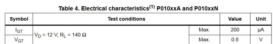
The thyristor, is simply used as a "comparator", with its VGT voltage (0.8V) as the reference.
There is a sense resistor in the mains neutral, and this sense voltage is fed to the thyristor's Gate-cathode terminal.
If a short cct current occurs, the thyristor breaks over and pulls current through an opto which results in a comparator
getting tripped and turning off the back2back NFETs.
Advantage is that its obviously an AC power circuit, and the thyristor can trip whether the current is going one way or t'other
in the sense resistor.
As can be seen from fig13 of the datasheet, the VT of the thyristor can be anywhere from 0.8V to 1.4V from 25degC to 125degC.
Indeed, from batch to batch, this can be different. As such, would you agree, this method of protection is
simply unwise?
..The poor , back2back SiHG70N60 NFETs will simply not be tripped in a timely fashion when a short cct occurs...and they will explode.
Would you agree, what is in fact needed is to use back2back IGBTs instead, and simply use a proper window comparator with +/-
supplies to detect overcurrent in the sense resistor. (obviously its AC mains current in the sense resistor, hence the window comparator with +/- supplies.)
P102AA thyristor datasheet
SiHG70N60 FET
Our client is using the P102AA thyristor to give short circuit protection in their AC mains circuit.
Its a trailing edge phase cutting heater regulator.
(The phase cutting is simply done with the switching of the back-to-back NFETs.)
As you can imagine, short cct protection involves promptly turning off these NFETs.
The thyristor, is simply used as a "comparator", with its VGT voltage (0.8V) as the reference.
There is a sense resistor in the mains neutral, and this sense voltage is fed to the thyristor's Gate-cathode terminal.
If a short cct current occurs, the thyristor breaks over and pulls current through an opto which results in a comparator
getting tripped and turning off the back2back NFETs.
Advantage is that its obviously an AC power circuit, and the thyristor can trip whether the current is going one way or t'other
in the sense resistor.
As can be seen from fig13 of the datasheet, the VT of the thyristor can be anywhere from 0.8V to 1.4V from 25degC to 125degC.
Indeed, from batch to batch, this can be different. As such, would you agree, this method of protection is
simply unwise?
..The poor , back2back SiHG70N60 NFETs will simply not be tripped in a timely fashion when a short cct occurs...and they will explode.
Would you agree, what is in fact needed is to use back2back IGBTs instead, and simply use a proper window comparator with +/-
supplies to detect overcurrent in the sense resistor. (obviously its AC mains current in the sense resistor, hence the window comparator with +/- supplies.)
P102AA thyristor datasheet
SiHG70N60 FET