Continue to Site

Welcome to EDAboard.com

Welcome to our site! EDAboard.com is an international Electronics Discussion Forum focused on EDA software, circuits, schematics, books, theory, papers, asic, pld, 8051, DSP, Network, RF, Analog Design, PCB, Service Manuals... and a whole lot more! To participate you need to register. Registration is free. Click here to register now.

Thermocouple Amplifier using LM 358

Status
Not open for further replies.

imvirang

Newbie level 3
Joined
Jul 19, 2016
Messages
4
Helped
0
Reputation
0
Reaction score
0
Trophy points
1
Activity points
26
Hello,

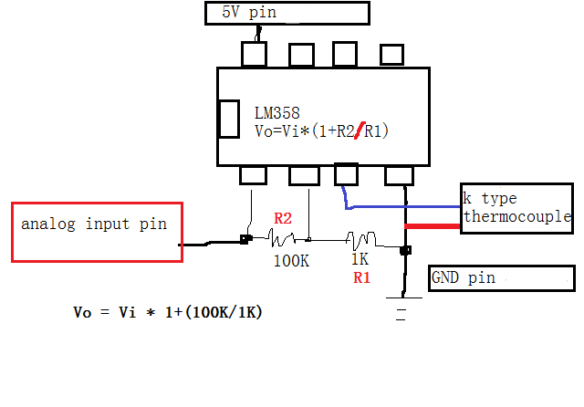
i am working on Thermocouple Amplifier from amb to 350 deg. using LM 358.
But there is some fluation problem.
i am using K type Thermocouple.
So will you please help me??
 

Hi,

A thermocouple type K has about 0.04mV/°C.

Your LM324 has a typical input offset voltage of about 2mV
--> this makes an offset in temperature of about 2mV/0.04mV/°C = 50°C

The offset voltage drift of your LM358 is about 7uV/°C.
Compared with the voltage of the tyke K element it generates only a drift of 7uV/°C / 0.04mV/°C = 0.16°C/°C

This is all we can tell because you don´t give more informations.

**********
For further posting please give all informations:
* You circuit/schematic with part values
* What (ouput) do you expect? In values with units.
* What does happen instead? (Best also with values and units).
* How do you observe your signals? DVM, scope, ADC, microcontroller?
* Do you have filters installed? (Filters for supply voltage, for temperature signal, analog filters, digital filters ....)

--> fluctuation of an analog signal is quite normal. But what size does it fluctuate? Only some 0.1°C or does it fluctuate about 100°C?
And in what itme? Does it fluctuate 10°C within milliseconds or 0.1°C within hours?

And how do you measure the fluctuation? DVM.


Klaus


*****


Here i have attached my circuit.
i measure using DVM as well as microcontroller.
Supply is 5V from regulator.
Output voltage of LM 358 has been vary within 50 to 100 mV.
Output has not been stable.
its continuous vary.
 

Hi,

There are some issues:
* Don´t leave the second OPAMP (pins 5, 6, 7) unconnected.
* You don´t have negative supply, therefore you may have unpredictable results with low and negative (differential) temperatures.
* I´m missing cold junction compensation / absolute temperature measurement.
* low pass filter(s) are missing. --> try to connect a 10uF (1uF at least) foil capacitor across the 100k.

*************
A change in 50mV represents a change in about 12°C.

*************
As said... A measurement around room temperature is not possible, therefore:
Try to put the sensor into boiling water. (about 100°C)
With a cold junction temperature of 25°C you may expect about 300mV of output voltage.
What does it show?

Klaus


can u explain with circuit diagram?
i dont understand about pin 5,6,7 unconnected?
wat is connection diagram for my application?
 

Hi,

One possible solution:
three resistors. Let´s take 10k each:
1) pin6 - R - pin7
2) GND - R - pin5
3) VCC - R - pin5

Klaus
 

Hi,

One possible solution:
three resistors. Let´s take 10k each:
1) pin6 - R - pin7
2) GND - R - pin5
3) VCC - R - pin5

Klaus


Ohk i will check it and reply you.

i have a same problem in PT 1000 circuit.
when i start my product there is fluation in amb temp.
thn it has been vary withn +/- 5 deg.


May i have solution ?
 

There are no indications of a specific reason for the observed fluctuations. Most likely reasons are unreliable circuit wiring (e.g. breadboard) or unstable supply voltage.
 

Status
Not open for further replies.

Similar threads

Part and Inventory Search

Welcome to EDABoard.com

Sponsor

Back
Top